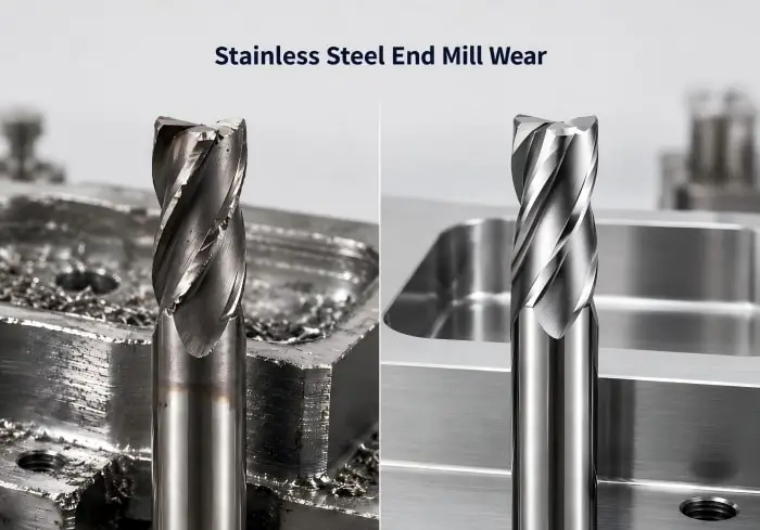
Why Do End Mills Wear Quickly When Milling Stainless Steel? Causes and Solutions
August 24, 2026Stainless steel can be more demanding on carbide end mills than many general steels. A cutter that provides stable tool life in carbon steel may show faster flank wear, edge chipping or inconsistent performance when used under similar conditions in stainless steel.
The reason is not simply that stainless steel is “hard.” Depending on the grade, the cutting edge may face work hardening, concentrated cutting heat, ductile chips, material adhesion and changing cutting forces at the same time.
Therefore, when an end mill wears quickly in stainless steel, increasing coating hardness or reducing feed alone may not solve the problem. Tool geometry, cutting conditions, chip evacuation, rigidity and the actual stainless steel grade should be evaluated together.
For a broader material comparison, see ZHY’s guide to choosing carbide end mills by workpiece material.
Why Is Stainless Steel Difficult on Carbide End Mills?
Stainless steel includes many different grades, so machining behavior is not identical across the entire material group. However, several characteristics commonly make stainless steel demanding during milling.
These include:
- Local work hardening
- Concentrated cutting heat
- Ductile and difficult-to-control chips
- Material adhesion around the cutting edge
- Relatively high cutting forces
- Sensitivity to rubbing and unstable engagement
- Increased risk of vibration with long tool overhang
The tool must therefore continue cutting cleanly while maintaining enough strength to withstand repeated mechanical and thermal loads.
A geometry that is too blunt can increase rubbing and cutting resistance. However, an excessively weak cutting edge may chip under heavier engagement.
The correct tool needs a balance between cutting-edge sharpness, carbide strength, chip space and overall rigidity.
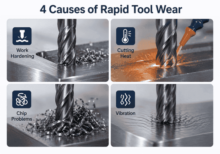
How Work Hardening Accelerates End Mill Wear
Work hardening is one of the most important problems to understand when milling many stainless steel grades.
When the cutting edge removes material efficiently, it continuously enters fresh workpiece material and forms a chip.
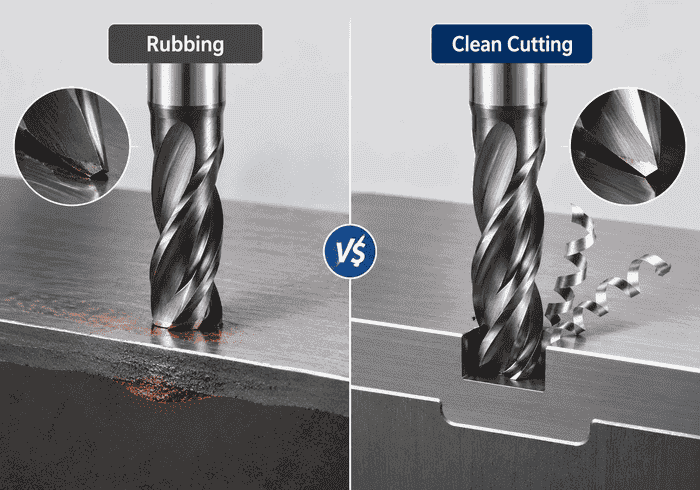
Problems begin when the edge rubs, dwells or repeatedly passes over a surface without removing enough material.
The locally deformed surface can become harder than the surrounding material. On the following pass, the cutter then needs to machine this hardened layer.
As a result, cutting forces and edge wear can increase.
Conditions That Can Encourage Work Hardening
Typical causes include:
- Excessively light feed
- Dull cutting edges
- Tool rubbing instead of shearing
- Repeated passes over the same surface
- Unstable tool engagement
- Dwelling at the bottom of a cut
- Excessive vibration or deflection
This is why simply reducing feed every time the cutting sound becomes heavy can sometimes make the problem worse.
The cutter still needs sufficient chip load to maintain a clean cutting action.
Why Cutting Heat Causes Rapid Tool Wear
Stainless steel machining can concentrate significant heat around the cutting edge and chip-tool contact zone.
When heat remains close to the cutting edge, several problems may develop:
- Faster coating wear
- Accelerated flank wear
- Edge softening at elevated temperature
- Increased material adhesion
- Unstable surface quality
- Greater sensitivity to local chipping
The solution is not simply to flood the area with more coolant. Heat generation also depends on cutting geometry, engagement, chip formation and whether chips leave the cutting zone efficiently.
A properly formed chip carries part of the generated heat away from the workpiece and cutter.
Therefore, chip formation and chip evacuation should be considered part of thermal control.
Why Chip Evacuation Matters in Stainless Steel Milling
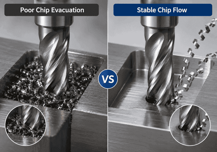
Stainless steel often produces ductile chips that can be more difficult to control than short, brittle chips.
If chips remain inside a slot or pocket, the following flute may cut through them again.
This chip recutting can increase:
- Cutting resistance
- Cutting temperature
- Edge wear
- Surface scratching
- Vibration
- Risk of edge chipping
The problem becomes more serious during full-slot milling because a large portion of the cutter remains surrounded by workpiece material.
Deep pockets create another challenge because chips must travel farther before leaving the cutting zone.
Therefore, always check whether the available flute space matches the amount of material being removed.
How Flute Count Affects Stainless Steel Milling
Flute count changes the balance between chip space, cutting-edge quantity and tool-core rigidity.
A lower flute count generally provides more open space for chips. In comparison, a higher flute count provides additional cutting edges and can allow a stronger core depending on the geometry.
However, there is no rule that every stainless steel application should always use the same flute count.
Full-Slot Milling
Chip evacuation becomes a major priority because the cutter is heavily surrounded by material.
The tool needs enough flute capacity to prevent chips from becoming trapped.
Side Milling
Because radial engagement is lower, chip evacuation is generally less restrictive.
This can allow a cutter with more cutting edges to operate effectively while maintaining good rigidity.
Dynamic Milling
Controlled radial engagement can reduce sudden cutting loads and help maintain more consistent chip thickness.
This type of machining can benefit from geometry designed for stable engagement and vibration control.
For a more detailed comparison, see ZHY’s guide to 2-flute, 3-flute and 4-flute end mills.
Why Tool Geometry Matters for Stainless Steel
A stainless steel end mill should not be selected by coating alone.
The geometry underneath the coating determines how the cutter enters the material, forms the chip and carries cutting forces.
Several features are especially important.
Positive Cutting Geometry
A suitable positive rake can reduce cutting resistance and support cleaner chip formation.
This is useful when the goal is to avoid unnecessary rubbing and local work hardening.
However, the edge still needs enough strength for the required cutting load.
Chip Space
The flute must provide sufficient volume for the chips generated during the operation.
This becomes particularly important during slots, deep pockets and roughing.
Core Rigidity
A rigid tool body helps control deflection during higher cutting loads.
However, increasing the core diameter also reduces flute space.
Therefore, chip capacity and tool rigidity must be balanced rather than maximized independently.
Unequal Cutting Geometry
Unequal tooth spacing or variable cutting geometry can change the timing of cutting-edge engagement.
This can help interrupt repetitive cutting forces and support more stable machining when vibration is a concern.
ZHY’s carbide end mills for stainless steel are designed around chip evacuation, cutting stability and stainless-steel-specific cutting geometry for roughing, dynamic milling, side milling and controlled semi-finishing.
How Coating Affects Tool Life in Stainless Steel
A suitable coating helps protect the carbide surface from wear, cutting heat and oxidation.
However, coating should be viewed as part of the complete tool design.
For example, a heat-resistant coating cannot compensate for:
- Severe chatter
- Excessive runout
- Poor chip evacuation
- An unsuitable rake angle
- Excessive tool overhang
- Cutting parameters that cause rubbing
Likewise, a high-quality coating can still wear quickly when the cutting edge repeatedly contacts a work-hardened surface.
Therefore, first confirm that the tool geometry and machining conditions match the application.
Then evaluate whether the coating provides suitable wear and thermal resistance.
For more detail, see ZHY’s guide to end mill coatings for different materials.
How Chatter Accelerates Stainless Steel End Mill Wear
Chatter creates repeated changes in cutting load.
Instead of each flute entering the workpiece under controlled conditions, the cutting edge experiences alternating engagement and impact.
This can create:
- Irregular edge wear
- Micro-chipping
- Surface vibration marks
- Uneven flute loading
- Increased cutting noise
- Reduced tool life
Stainless steel can make this problem more severe because the tool may already be operating under relatively high cutting and thermal loads.
Common causes include:
- Excessive tool overhang
- Weak workholding
- Poor toolholder condition
- Unstable spindle speed
- Heavy radial engagement
- Thin or flexible workpiece features
When vibration marks or abnormal cutting noise appear together with rapid wear, the machining system should be checked before simply replacing the cutter.
See the ZHY guide to end mill chatter and vibration for a more detailed troubleshooting process.
How Runout Creates Uneven Tool Wear
Ideally, all flutes should share the cutting load as evenly as possible.
Runout changes this balance.
When one flute projects farther than the others, that cutting edge removes a larger chip. Meanwhile, the remaining flutes remove less material.
The overloaded flute may then show:
- Faster flank wear
- Local edge chipping
- Higher cutting temperature
- Greater risk of premature failure
When one flute consistently wears faster than the others, inspect:
- Toolholder cleanliness
- Collet condition
- Tool shank
- Spindle interface
- Clamping condition
- Tool runout near the cutting edge
Repeatedly replacing the end mill will not solve a runout problem in the holder or spindle.
How Cutting Parameters Affect Tool Wear
Cutting speed, feed and engagement should be evaluated together.
Changing only one parameter without considering the others can create a new problem.
Feed per Tooth Too Low
An excessively light chip load can increase rubbing.
In stainless steel, this may contribute to local work hardening and additional edge wear.
Feed per Tooth Too High
Excessive chip thickness increases mechanical loading on each cutting edge.
This can cause accelerated wear or chipping.
Excessive Radial Engagement
Heavy radial engagement increases cutting force and heat.
When the tool also has long overhang, the risk of deflection and vibration rises further.
Excessive Axial Depth
A larger axial depth increases the length of cutting edge engaged in the workpiece.
This can improve productivity when the system is stable, but it also increases total tool loading.
Cutting Speed
Excessive cutting speed can accelerate thermal wear.
However, reducing speed blindly is not always the answer because the feed relationship and chip formation also change.
The correct parameter adjustment should therefore consider the entire cutting condition.
304 vs 316 Stainless Steel: Should the Same End Mill Be Used?
304 and 316 are both widely machined austenitic stainless steels, but machining behavior can vary with material condition, batch, workpiece geometry and cutting operation.
Therefore, the same end mill family may be suitable for both materials, but identical cutting parameters should not automatically be assumed.
When changing from one stainless grade to another, check:
- Actual workpiece grade
- Material condition
- Tool wear pattern
- Chip formation
- Cutting sound
- Spindle load
- Surface finish
- Required tool life
For production applications, small parameter adjustments may be necessary even when the same cutter geometry is retained.
The same principle applies to 304L, 316L, 321, 17-4PH, duplex and martensitic stainless steels.
The exact grade should always be confirmed before selecting the final machining conditions.
How to Reduce End Mill Wear in Stainless Steel
When tool life is shorter than expected, check the machining system in a consistent order.
Step 1: Inspect the Wear Pattern
Determine whether the main problem is:
- Flank wear
- Edge chipping
- Material adhesion
- Uneven flute wear
- Heat-related damage
- Complete fracture
Different failure patterns point toward different causes.
Step 2: Confirm the Stainless Steel Grade
Do not diagnose the application based only on the description “stainless steel.”
Confirm the actual grade and material condition.
Step 3: Check the Cutting Edge
A dull or damaged tool can begin rubbing and accelerate work hardening.
Step 4: Inspect Chip Evacuation
Check whether chips remain in slots, pockets or deep cavities.
Step 5: Check Tool Overhang
Reduce projection whenever the component geometry allows it.
Step 6: Check Runout
Uneven flute wear is a strong reason to inspect toolholding and runout.
Step 7: Review Cutting Engagement
Check radial and axial depth together with the available machine and tool rigidity.
Step 8: Review Feed and Speed
Make sure the cutter continues forming a stable chip instead of rubbing.
Step 9: Confirm Tool Geometry
The carbide substrate, flute geometry, rake, core structure and coating should match stainless steel machining rather than a very different material group.
If severe wear has already progressed into repeated edge chipping or fracture, see the ZHY guide to carbide end mill breakage.
Stainless Steel End Mill Wear Troubleshooting Table
| Symptom | Possible Cause | First Check |
|---|---|---|
| Rapid Flank Wear | Heat, abrasive wear or unsuitable cutting conditions | Cutting speed, coating and tool condition |
| Edge Chipping | Vibration, excessive load or unstable engagement | Rigidity, tool overhang and engagement |
| One Flute Wears Faster | Runout or uneven flute loading | Toolholder, collet and spindle runout |
| Material on Cutting Edge | Adhesion or unstable chip formation | Edge geometry, chip flow and cutting conditions |
| Chips Packed in Flutes | Insufficient chip evacuation | Flute space, depth of cut and chip removal |
| Vibration Marks and Wear | Chatter or weak machining setup | Tool overhang, fixture and spindle speed |
| Wear After Repeated Light Passes | Rubbing or local work hardening | Feed per tooth and cutting-edge condition |
Frequently Asked Questions
Why Does My End Mill Wear So Fast in 304 Stainless Steel?
Rapid wear can result from work hardening, cutting heat, poor chip evacuation, excessive cutting speed, rubbing or unsuitable tool geometry. Check the wear pattern before changing several parameters at once.
Does Stainless Steel Work Harden During Milling?
Many stainless steel grades can work harden when the surface undergoes repeated deformation or rubbing. Maintaining a clean cutting action helps reduce repeated contact with a locally hardened surface.
Should I Reduce Feed When Milling Stainless Steel?
Not automatically. Excessive feed can overload the cutting edge, but feed that is too low may cause rubbing. Feed per tooth should support stable chip formation.
What Flute Count Is Best for Stainless Steel?
There is no single flute count for every stainless steel operation. Full-slot milling requires more attention to chip space, while side and dynamic milling can use different balances between flute count and tool rigidity.
Can Coating Improve Tool Life in Stainless Steel?
Yes, a suitable coating can improve wear and thermal resistance. However, coating cannot correct severe chatter, runout, poor chip evacuation or unsuitable cutting geometry.
Why Does Only One Flute Wear Quickly?
This often indicates uneven flute loading. Toolholder condition, collet condition and runout should be checked.
Can Work Hardening Cause End Mill Breakage?
Work hardening can increase the load on the cutting edge. When combined with vibration, excessive engagement or an already damaged tool, it can contribute to edge chipping and eventual breakage.
Conclusion
Rapid carbide end mill wear in stainless steel is rarely caused by one factor alone.
Work hardening, concentrated cutting heat, difficult chip evacuation, material adhesion, vibration and runout can act together and shorten tool life.
Start by identifying the actual wear pattern. Then confirm the stainless steel grade, cutting-edge condition, chip evacuation, tool overhang and runout before making large parameter changes.
A suitable stainless steel end mill should balance sharp cutting action, chip space, tool-core rigidity, coating performance and vibration control.
For applications involving 304, 316, 17-4PH, duplex stainless steel, long-reach machining or non-standard dimensions, ZHY can review the workpiece grade, machining operation, tool size and production requirements and provide standard or customized carbide end mill solutions.