End Mill Chatter: Causes and Prevention in CNC Milling
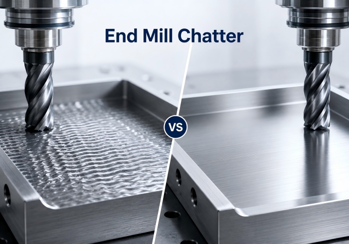
August 12, 2026End mill chatter is an unstable vibration that occurs when the cutting tool, workpiece and machine system cannot maintain consistent cutting engagement.
It often appears as a repeating cutting noise, wave-like marks on the machined surface or fluctuating cutting load. If the vibration continues, it can reduce surface quality, accelerate tool wear and even contribute to edge chipping or tool failure.
The cause is not always the end mill itself. Tool overhang, workholding rigidity, spindle speed, cutting engagement, runout and chip evacuation all influence machining stability. The most effective solution is to identify the source of vibration before changing multiple parameters at the same time.
What Is End Mill Chatter?
End mill chatter is a self-excited vibration that develops during milling when cutting forces repeatedly cause the tool or workpiece to deflect and re-engage with the cut.
Unlike normal cutting vibration, chatter tends to repeat and amplify.
As the cutting edge enters and leaves the workpiece, unstable forces can create a cycle of vibration that affects both the cutter and the machined surface.
Typical Signs of End Mill Chatter
Common signs include:
- Repeating or high-pitched cutting noise
- Wave-like marks on the machined surface
- Poor or inconsistent surface finish
- Uneven tool wear
- Fluctuating spindle load
- Visible tool vibration during cutting
If these symptoms appear together, the machining system should be checked before simply replacing the end mill.
What Causes End Mill Chatter? 7 Main Causes
End mill chatter usually develops from a combination of tool rigidity, machining parameters and setup conditions.
The following seven causes are the most important to check.
1. Excessive Tool Overhang
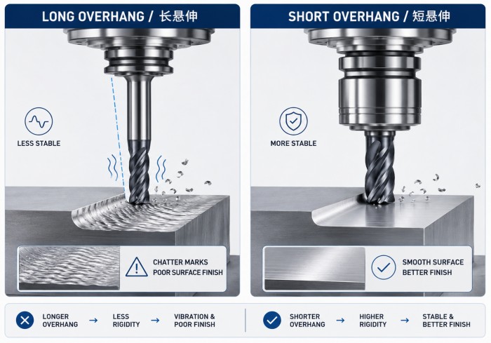
Tool overhang is one of the most common causes of milling vibration.
As the distance between the toolholder and cutting edge increases, the cutter becomes less rigid and more sensitive to cutting forces.
Long overhang can increase:
- Tool deflection
- Vibration amplitude
- Surface waviness
- Cutting-edge stress
The shortest possible tool projection should normally be used while still allowing access to the machining area.
For deep cavities and difficult-to-reach features, tool reach must be balanced against rigidity. Our guide to deep cavity and long-reach milling explains how standard, long-flute and long-neck tools differ.
2. Weak Toolholding or Workholding
Chatter can occur even when the end mill itself is rigid if the rest of the machining system is unstable.
Possible sources include:
- Insufficient clamping force
- Long toolholder projection
- Poor collet condition
- Weak fixture support
- Thin or flexible workpieces
- Machine structural vibration
The cutter, holder, spindle, fixture and workpiece should be considered as one system.
Improving overall rigidity is often more effective than changing the cutter alone.
3. Unstable Spindle Speed and Feed Rate
Spindle speed affects how frequently the cutting edges engage with the workpiece.
At certain speeds, the cutting frequency can interact with the natural vibration of the machine-tool system and increase chatter.
Feed rate also affects cutting load.
Too much feed can overload the cutting edge, while extremely light feed may cause rubbing rather than efficient chip formation.
When chatter appears, spindle speed should be adjusted in controlled steps rather than changing several parameters randomly.
For more detailed parameter selection, see our carbide end mill speeds and feeds guide.
4. Excessive Radial or Axial Engagement
Heavy cutting engagement increases cutting force.
If radial width of cut or axial depth is too aggressive for the rigidity of the setup, the end mill may begin to deflect and vibrate.
High engagement is particularly sensitive when combined with:
- Long tool overhang
- Small tool diameter
- Weak workholding
- Deep slotting
- Difficult-to-machine materials
Reducing cutting engagement can often improve stability without requiring a complete change of tool.
5. Unsuitable End Mill Geometry
End mill geometry affects how cutting forces are distributed during each tooth engagement.
Important features include:
- Flute count
- Helix angle
- Pitch
- Core diameter
- Rake angle
- Cutting-edge strength
A tool with insufficient core rigidity may deflect more easily.
Likewise, equally spaced cutting edges can sometimes reinforce vibration under specific cutting conditions.
Variable pitch or unequal helix geometry can help interrupt repeated cutting-force patterns and improve machining stability.
6. Tool Runout
Runout causes individual cutting edges to remove different amounts of material.
Instead of sharing the cutting load evenly, one flute may carry more load than the others.
This can result in:
- Uneven tool wear
- Periodic cutting force
- Vibration
- Poor surface quality
Runout can come from the cutter, collet, holder, spindle or contamination between clamping surfaces.
When chatter appears repeatedly with new tools, toolholding and runout should be checked carefully.
7. Poor Chip Evacuation
Chips that remain in the cutting zone may be recut by the end mill.
This creates irregular cutting forces and can increase vibration.
Chip evacuation becomes especially important during:
- Slot milling
- Deep cavity machining
- Aluminum machining
- High material removal operations
Flute space, coolant or air supply and toolpath strategy should all support effective chip removal.
How to Reduce End Mill Chatter: 6 Practical Steps
Once chatter is identified, changes should be made systematically.
Changing several variables at once makes it difficult to determine which factor actually solved the problem.
Step 1: Shorten Tool Overhang
Reduce tool projection as much as the workpiece geometry allows.
A shorter tool setup increases rigidity and reduces deflection.
Step 2: Improve Tool and Workpiece Rigidity
Check:
- Toolholder condition
- Collet clamping
- Fixture support
- Workpiece clamping
- Machine condition
Flexible workpieces may also require additional support.
Step 3: Adjust Spindle Speed in Controlled Steps
A moderate RPM change can shift the cutting system away from an unstable vibration range.
Do not assume that lower spindle speed always reduces chatter.
In some cases, a different higher or lower speed may produce better stability.
Step 4: Reduce Radial or Axial Engagement
If cutting forces are too high, reduce width of cut or depth of cut.
This is particularly useful for:
- Long-reach tools
- Small-diameter cutters
- Deep slots
- Thin-wall components
Step 5: Improve Chip Evacuation
Prevent chips from remaining in the cutting zone.
Check:
- Flute space
- Coolant direction
- Air blast
- Toolpath
- Pocket and slot geometry
Step 6: Check Runout and Tool Condition
Inspect the cutter and toolholding system for:
- Edge wear
- Edge chipping
- Runout
- Collet wear
- Improper clamping
A worn or unevenly loaded tool can continue to chatter even after cutting parameters are adjusted.
End Mill Chatter Troubleshooting Guide
| Symptom | Possible Cause | First Action |
|---|---|---|
| High-pitched repeating noise | Unstable spindle speed or cutting engagement | Adjust RPM in controlled steps |
| Wave marks on machined surface | Long overhang or weak rigidity | Shorten tool projection and improve support |
| One flute wears faster | Runout or uneven tool loading | Check holder, collet and spindle runout |
| Chatter in deep cavities | Long reach and reduced rigidity | Use the shortest practical reach |
| Chatter during slot milling | High engagement or chip congestion | Reduce load and improve chip evacuation |
| Chatter near corners | Sudden increase in radial engagement | Adjust toolpath and reduce corner load |
How End Mill Geometry Helps Control Chatter
When machine setup and cutting parameters are reasonable but chatter still occurs, cutter geometry should be considered.
Unequal Pitch and Unequal Helix Geometry
Equal tooth spacing creates regular cutting-force intervals.
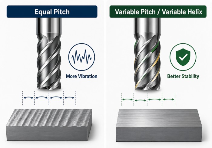
Under certain machining conditions, this repeated force pattern may reinforce vibration.
Unequal pitch and variable helix designs change the timing and direction of cutting forces.
This can help interrupt the vibration cycle and improve cutting stability.
Core Diameter and Tool Rigidity
A larger core generally provides greater bending stiffness.
This is particularly important for:
- Long tools
- Deep cavity machining
- Hard materials
- High cutting loads
However, increasing core diameter reduces flute space, so tool design must also consider chip evacuation.
Flute Count
More flutes can increase cutting-edge engagement and support higher feed rates, but they also reduce chip space.
Fewer flutes provide more room for chip evacuation.
The best flute count depends on workpiece material, cutting operation and required rigidity.
How Workpiece Material Affects Chatter
Different materials create different cutting-force and chip-formation conditions.
Material and Chatter Risk Table
| Material | Typical Chatter Risk | Main Consideration |
|---|---|---|
| Aluminum | Built-up edge and chip accumulation | Sharp geometry and chip evacuation |
| Stainless Steel | Heat and work hardening | Stable engagement and controlled cutting load |
| Titanium Alloy | High cutting force and concentrated heat | Rigid setup and suitable tool geometry |
| Hardened Steel | High edge load and rigidity demand | Strong core and stable toolholding |
Tool geometry and coating should therefore be selected according to the workpiece material rather than using one cutter design for every application.
For more information, see our guide to choosing carbide end mills by workpiece material.
Why Slot Milling Is More Prone to Chatter
Slot milling creates high cutting engagement because the cutter is often in contact with material on both sides.
This increases:
- Cutting force
- Chip volume
- Heat generation
- Risk of chip recutting
The problem becomes more severe in deep slots because chip evacuation becomes more difficult and longer tool reach may be required.
When chatter occurs during slotting, check:
- Radial engagement
- Tool overhang
- Flute space
- Chip evacuation
- Spindle speed
- Workpiece rigidity
When Is End Mill Geometry the Cause of Chatter?
If chatter continues after checking toolholding, workholding, runout, cutting parameters and chip evacuation, the cutter geometry may not match the application.
Important tool-selection factors include:
- Flute count
- Helix angle
- Unequal pitch
- Core diameter
- Rake angle
- Cutting length
- Neck length
- Overall tool reach
For example, a tool with excessive cutting length may have less rigidity than necessary, while a geometry designed for one material may create unstable cutting forces in another.
ZHY provides carbide end mill solutions with different flute, helix and core designs for different materials and CNC machining conditions.
For unusual reach, special geometry or applications where standard tools repeatedly produce unstable results, custom carbide end mills can be designed according to the workpiece and machining requirements.
FAQ
What Causes End Mill Chatter?
End mill chatter can be caused by excessive tool overhang, weak workholding, unstable spindle speed, heavy cutting engagement, unsuitable tool geometry, runout or poor chip evacuation.
How Do I Stop Chatter When Milling?
Start by shortening tool overhang and checking toolholding and workpiece rigidity. Then inspect runout, cutting engagement and chip evacuation before adjusting spindle speed in controlled steps.
Does a Longer End Mill Cause More Chatter?
A longer end mill is generally more flexible than a shorter tool of the same diameter. Excessive projection can increase deflection and make chatter more likely.
Should I Reduce RPM When an End Mill Chatters?
Not always. Chatter depends on the relationship between cutting frequency and system vibration. A controlled change in spindle speed, either higher or lower, may move the process into a more stable range.
Can Variable Helix End Mills Reduce Chatter?
Variable helix and unequal pitch designs can help reduce repeated cutting-force patterns and improve stability, especially when tool geometry is one of the main causes of vibration.
Conclusion
End mill chatter is usually the result of an unstable machining system rather than one isolated problem.
Excessive tool overhang, weak rigidity, unsuitable cutting parameters, runout, chip evacuation and cutter geometry can all contribute to vibration.
The most effective troubleshooting process is to check these factors systematically, beginning with the mechanical setup before making large changes to cutting parameters.
Selecting an end mill with suitable rigidity, flute geometry and reach can further improve machining stability and surface quality.
For special machining conditions or repeated vibration problems, contact our team for carbide end mill selection and customized tooling support.