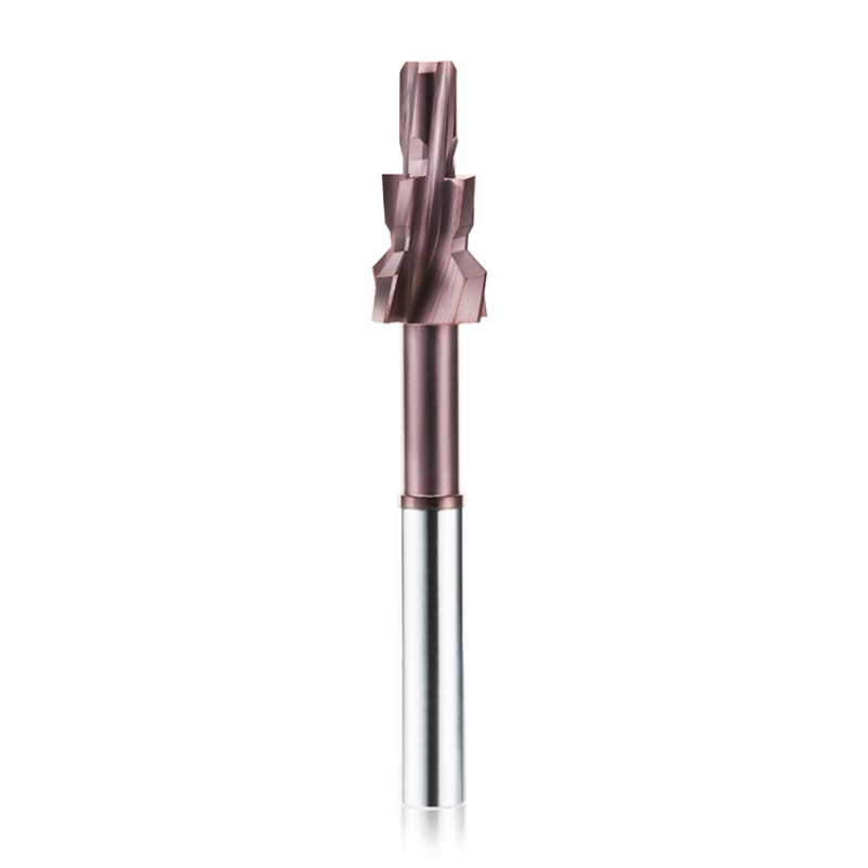
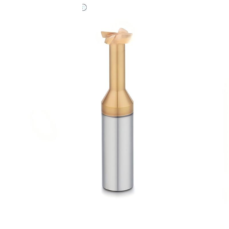
Custom Solid Carbide Form End Mill
Combines steps, shoulders, chamfers, radii, grooves and special profiles in one carbide tool to reduce separate machining operations.
View Custom CapabilitiesExplore drawing-based custom end mills and special-purpose milling cutters for form profiles, T-slots, undercuts, internal threads, chamfers, external radii, heavy roughing and application-specific machining processes. ZHY develops solid carbide and PCD tooling according to the component geometry, workpiece material, machine conditions and production requirements.
This range includes both fully drawing-based form tools and established special cutter structures that can be supplied in standard or customized dimensions.
These cutters are developed around a component profile or a combination of machining features.
These tools use a defined cutting structure for a particular machining operation, with dimensions and geometry adapted to the application.
Select these tools when the component requires a special contour, several connected dimensions, undercut access, a fixed external radius or application-specific cutting geometry.
Combines steps, shoulders, chamfers, radii, grooves and special profiles in one carbide tool to reduce separate machining operations.
View Custom Capabilities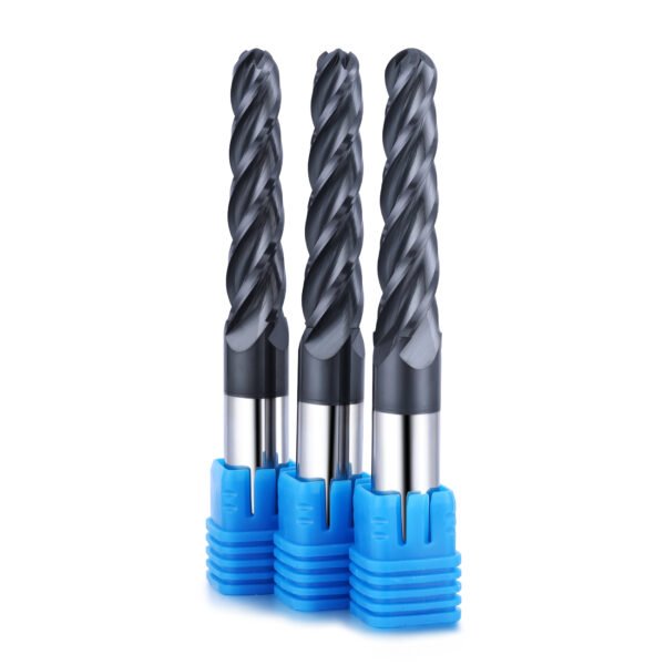
Custom tapered ball nose cutter for continuous aircraft-wing toolpaths, using an application-specific laser micro-groove beneath the helical section.
View Application Details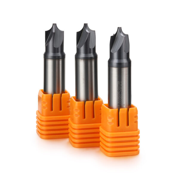
Concave-profile cutter for producing controlled external radii, rounded component edges and repeatable formed transitions.
View Radius Options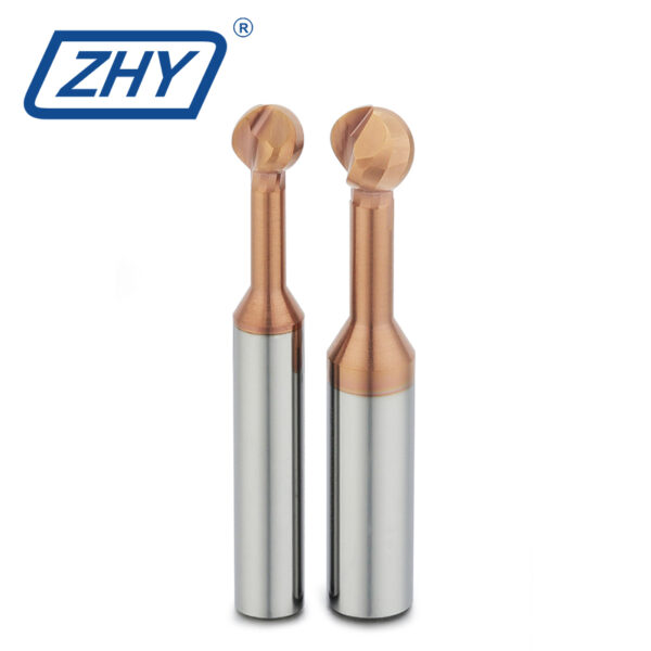
Spherical-head cutter for undercutting, back-side deburring, recessed surfaces and multi-axis contour machining.
View Undercutting Options
Drawing-based PCD cutter for profile and form milling of aluminum, non-ferrous materials and selected abrasive applications.
View PCD Tool DetailsThese tools are selected according to the machining operation and then customized for the required dimensions, workpiece material, tool access and production conditions.
Enlarged cutting head and relieved neck for T-slots, undercut grooves, recessed slots and precision clamping features.
View Custom Geometry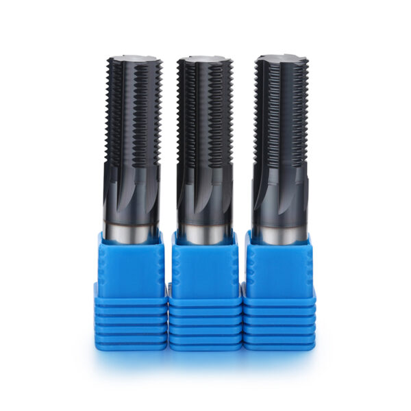
Multi-tooth carbide thread mill for precision internal threads using CNC helical interpolation in blind or through holes.
View Thread Options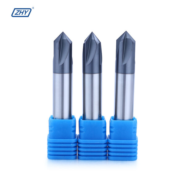
Carbide cutter for edge chamfering, deburring, hole-entry features and V-grooves, with standard and custom angle options.
View Angle Options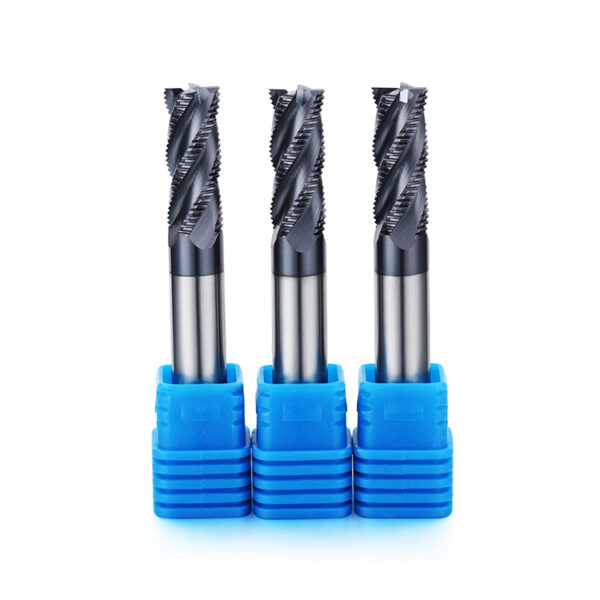
Coarse-serrated carbide rougher for efficient stock removal, cavity roughing, pocketing and side milling of steel and mold steel.
View Roughing Sizes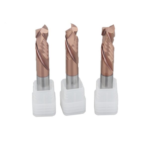
Opposite upcut and downcut flute sections for controlled top and bottom edges when machining laminated panels and selected composites.
View Compression GeometryStart with the component feature or machining operation. Then confirm workpiece material, dimensions, tolerance, tool access, machine conditions and production quantity.
Final geometry is reviewed according to the component, cutter strength, grinding feasibility, workpiece material and available machining conditions.
Steps, shoulders, radii, chamfers, grooves, undercuts and combination forms.
Cutter diameter, profile width, cutting length, step positions and form dimensions.
Neck diameter, neck length, relief form, tapered neck and extended reach.
Chamfer angles, taper angles, ball radii, corner radii and profile transitions.
Flute quantity, helix direction, rake geometry, chip space and end-cutting structure.
Solid carbide or PCD cutting structures selected according to material and production requirements.
Coating reviewed according to workpiece material, hardness, temperature and abrasiveness.
Customer model number, laser marking, labels and private-label packaging.
Provide the component or existing tool drawing together with the workpiece and machining information. Tool geometry is reviewed before prototype and batch production.
Review the component profile, dimensions, tolerances and machining feature.
Confirm material, hardness, machine, toolholder and cutting conditions.
Develop the profile, dimensions, flute structure and coating option.
Manufacture sample tools after the tool drawing is approved.
Inspect profile dimensions and verify machining performance when required.
Begin repeat production after the geometry and application are confirmed.
Complete information helps determine whether several features can be combined safely and whether a standard special cutter or a fully custom tool is more suitable.
Provide the required profile, workpiece material, dimensions, tolerances, machine information, current machining process and order quantity. ZHY will evaluate the tool structure and recommend a suitable solid carbide or PCD custom milling solution.