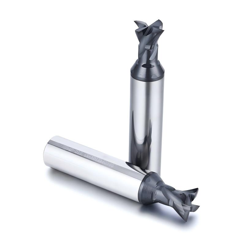
PCD Dovetail End Mills
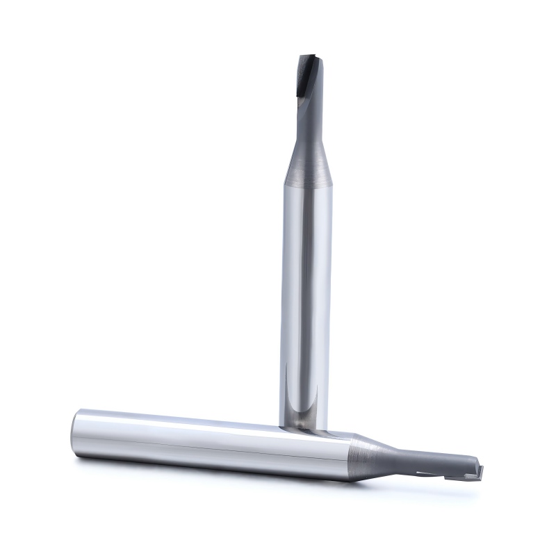
PCD dovetail end mills for precision machining of dovetail grooves, undercuts, angled sidewalls and locking profiles in aluminum, graphite, composites and other abrasive materials.
View SpecificationsZHY PCD milling tools are designed for precision machining of aluminum, high-silicon aluminum, copper alloys, graphite, fiber-reinforced composites, engineering plastics and other abrasive non-ferrous or non-metallic materials.
The range includes PCD dovetail end mills, drawing-based form milling cutters, chamfer cutters, slot and undercut tools, and single-edge PCD geometries for grooves, profiles, recessed features and combined machining operations.
Select the PCD milling tool according to the required groove, profile, chamfer, undercut, workpiece material and machining-access conditions.
PCD dovetail end mills for precision machining of dovetail grooves, undercuts, angled sidewalls and locking profiles in aluminum, graphite, composites and other abrasive materials.
View Specifications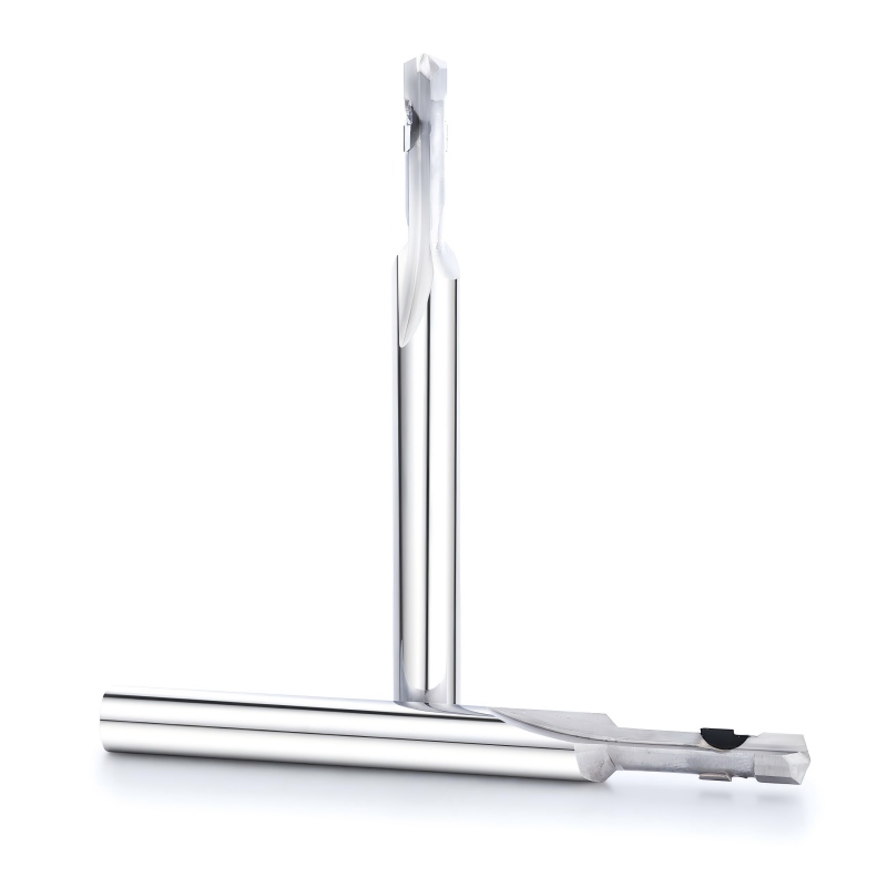
Drawing-based PCD profile, step, slot and undercut cutters for combined features, special grooves and application-specific machining operations.
View Specifications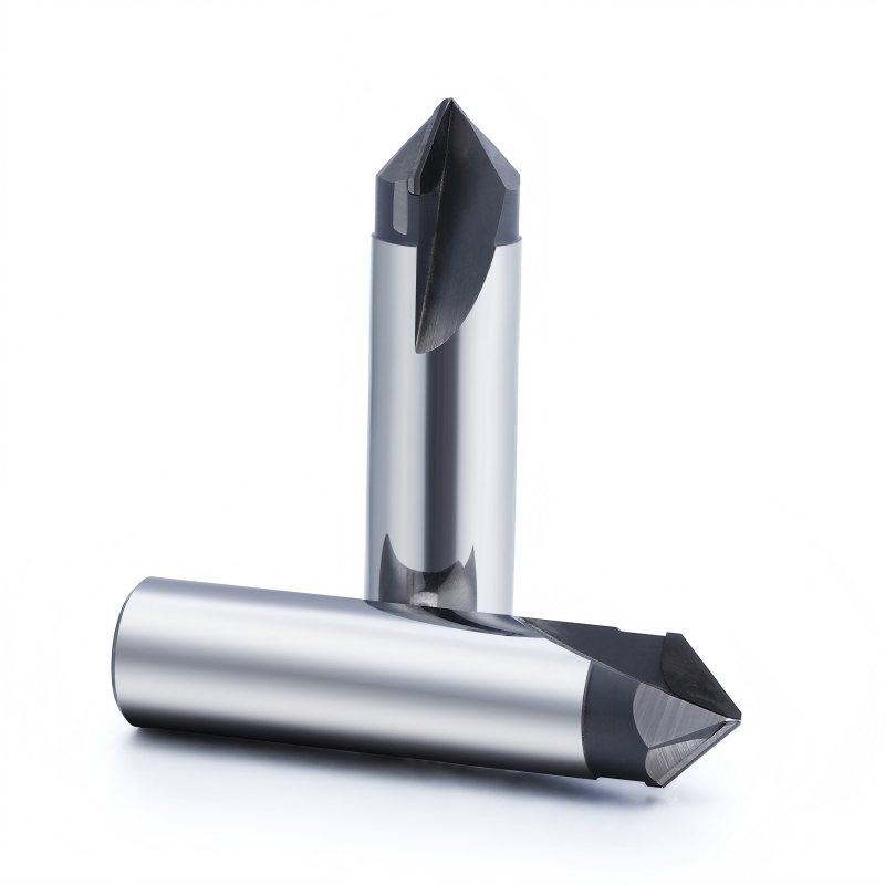
PCD chamfer cutters for hole-edge finishing, countersinking, deburring, V-grooves and precision angular features in abrasive non-ferrous materials.
View SpecificationsPCD milling tools are suitable for applications requiring high wear resistance, long-term cutting-edge retention and stable profile dimensions.
Precision machining of dovetail grooves, angled walls, locking profiles and recessed features.
Drawing-based machining of steps, grooves, contours, shoulders and combined component features.
Stable machining of hole edges, component edges, countersinks, V-grooves and angular profiles.
Long edge retention supports repeatable profile dimensions and fewer tool changes during production.
PCD milling tools are primarily intended for non-ferrous metals, graphite, composites and abrasive non-metallic materials.
PCD tools are generally not selected for hardened steel or most ferrous-material applications. CBN tools are normally more suitable for HRC60+ hardened ferrous materials.
PCD combines high abrasion resistance with stable cutting-edge retention, making it suitable for demanding non-ferrous and abrasive-material machining.
PCD cutting edges resist abrasive wear during machining of high-silicon aluminum, graphite, composites and other abrasive materials.
Stable cutting-edge geometry supports longer machining cycles and reduces frequent tool changes.
Sharp PCD cutting edges support low-resistance machining and help reduce burr formation in suitable non-ferrous materials.
Long-term edge retention helps maintain groove, chamfer and custom-profile dimensions during repeated machining.
PCD is particularly useful when silicon, graphite, carbon fiber or glass fiber accelerates conventional tool wear.
Cutting segments can be configured for dovetails, steps, grooves, undercuts, chamfers and combined features.
Extended edge retention can support longer unattended cycles and more stable batch production.
Selected PCD tools may be inspected for regrinding depending on cutting-edge wear, available material and tool construction.
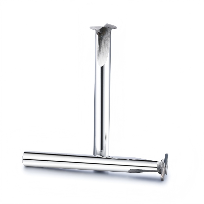
These tools demonstrate additional PCD cutting structures. Final geometry should be confirmed according to the component drawing, workpiece material and machining process.
Application-specific cutting heads can be developed for internal grooves, T-slot-type features, undercuts and recessed component profiles.
Single-edge or low-flute-count PCD geometries can provide increased chip space and low cutting resistance for selected aluminum and non-metallic-material applications.
Tool selection should be based on the machined feature, workpiece material, cutting direction, accessibility and dimensional requirements.
Tool dimensions and cutting geometries can be developed according to the component drawing, machine condition and production requirement.
Tool geometry is reviewed according to the workpiece feature, material, machine and cutting requirement before production.
Review the component drawing, required feature, tolerance and workpiece material.
Confirm the cutting profile, diameter, angle, length, clearance and edge quantity.
Produce prototype tools for dimensional and machining verification where required.
Confirm the final geometry, marking, packaging and production quantity.
Tool-body dimensions, PCD cutting-edge position and final profile geometry are checked to support repeatable custom and batch production.
ZHY supplies standard and customized PCD milling tools to cutting-tool distributors, component manufacturers, machining companies and private-label tool brands.
Send us the workpiece material, component drawing, machining feature, dovetail or chamfer angle, tool diameter, cutting width, profile dimensions, machine information, required tolerance and order quantity. Our team will review the application and recommend a suitable standard or customized PCD milling tool.
Request a PCD Tool Quote