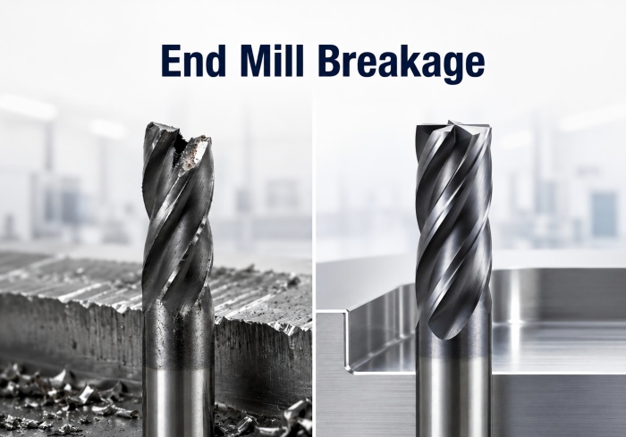
Why Do Carbide End Mills Break? Causes, Prevention & Troubleshooting
August 14, 2026A carbide end mill rarely breaks without a cause. In many cases, complete fracture is the final stage of a problem that has already developed through excessive cutting load, unstable vibration, chip congestion, runout or progressive edge damage.
Replacing the broken cutter without identifying the failure mechanism may cause the next tool to break in the same way. A better approach is to inspect the damaged tool first, then check rigidity, cutting engagement, chip evacuation, toolholding and whether the end mill is suitable for the workpiece and operation.
What Does End Mill Breakage Look Like?
End mill failure does not always begin with sudden complete fracture.
In many cases, the cutting edge shows early warning signs before the tool breaks.
Typical signs include:
- Small edge chipping
- Micro-cracks near the cutting edge
- Uneven flute wear
- Abnormal cutting noise
- Increasing spindle load
- Poorer surface finish
- Chips packing around the flute
Recognizing these symptoms early can help prevent complete tool failure and reduce unexpected machine downtime.
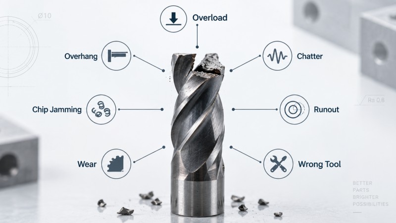
Why Do Carbide End Mills Break? 7 Main Causes
Most end mill breakage can be traced to cutting load, rigidity, toolholding, chip control or unsuitable tool selection.
1. Excessive Cutting Load
Carbide end mills are strong in compression but relatively brittle compared with high-speed steel tools.
If the cutting force exceeds the strength of the cutting edge or tool body, the tool may chip or fracture.
Common causes of excessive load include:
- Feed per tooth that is too high
- Excessive axial depth of cut
- Excessive radial engagement
- Sudden engagement in corners
- Unexpected hard areas in the workpiece
Heavy cutting conditions become even more dangerous when combined with long tool overhang or poor rigidity.
2. Excessive Tool Overhang
The farther an end mill extends from the holder, the more easily it can deflect under cutting force.
Long overhang increases bending stress and makes the cutter more sensitive to vibration and impact loading.
This becomes especially important during:
- Deep cavity machining
- Tall-wall machining
- Deep slot milling
- Long-neck or long-reach applications
The shortest practical tool projection should normally be used.
For deeper features, our guide to deep cavity and long-reach milling explains how tool reach can be balanced with rigidity.
3. Chatter and Vibration
Chatter creates repeated impact loading on the cutting edges.
Instead of removing material under stable force, the cutter repeatedly deflects and re-enters the workpiece.
This can accelerate:
- Edge chipping
- Uneven flute wear
- Surface damage
- Complete tool fracture
If vibration is the main problem, see our guide to end mill chatter for detailed troubleshooting.
4. Chip Jamming and Recutting
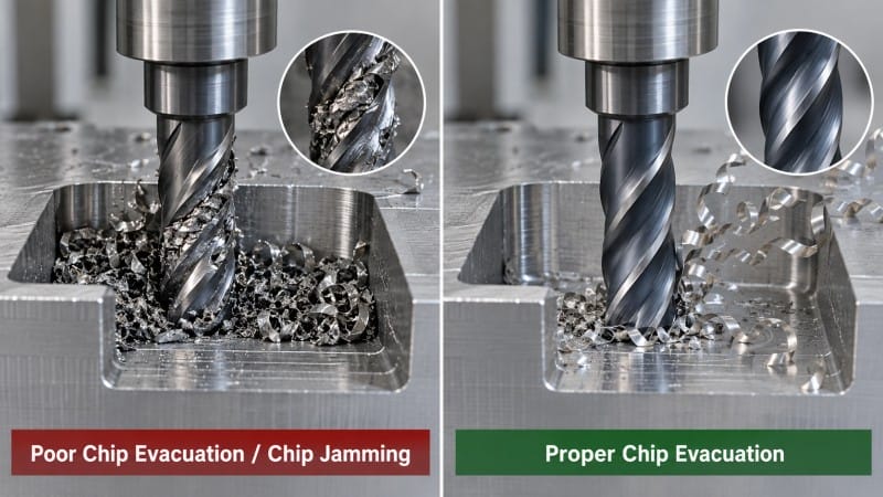
Chips that remain in the cutting zone can become trapped between the tool and the workpiece.
When the cutter strikes packed or recut chips, the cutting load can increase suddenly.
This is particularly common during:
- Slot milling
- Deep pockets
- Aluminum machining
- High material removal operations
Poor chip evacuation can therefore cause sudden tool breakage even when the programmed feed and speed appear reasonable.
Flute space, coolant direction, air blast and toolpath design should all support effective chip removal.
5. Runout and Poor Toolholding
Tool runout causes the flutes to carry unequal cutting loads.
Instead of each cutting edge removing a similar amount of material, one flute may remove significantly more.
This can create:
- Uneven wear
- Periodic cutting force
- Edge overload
- Chipping
- Premature breakage
Runout may come from the cutter, collet, holder, spindle or contamination between clamping surfaces.
When several new end mills fail in a similar way, toolholding and spindle runout should be checked before blaming the cutter itself.
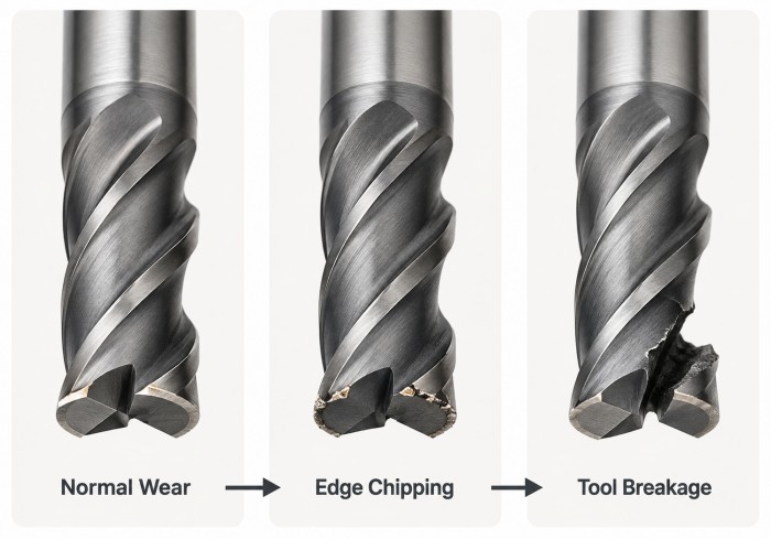
6. Progressive Tool Wear
End mills do not always fail immediately.
Normal wear can gradually increase cutting resistance.
As the cutting edge becomes dull:
Normal Wear
↓
Higher Cutting Load
↓
Edge Chipping
↓
Uneven Flute Loading
↓
Tool Breakage
Continuing to machine after the cutting edge has deteriorated significantly can turn normal wear into catastrophic failure.
Coating and carbide substrate can influence wear resistance, but the correct coating still needs to match the material and cutting condition. See our end mill coatings guide for more detail.
7. Wrong End Mill Selection
Sometimes the machining parameters are not the main problem.
The cutter itself may not be suitable for the application.
Important tool-selection factors include:
- Cutter diameter
- Core diameter
- Flute count
- Cutting length
- Helix angle
- Edge geometry
- Coating
- Carbide substrate
- Workpiece material
For example, a tool with excessive cutting length may have lower rigidity than necessary, while an unsuitable flute design may reduce chip evacuation.
Material-specific tool selection is explained further in our guide to choosing carbide end mills by workpiece material.
End Mill Breakage Troubleshooting Guide
| Symptom | Likely Cause | First Check |
|---|---|---|
| Sudden complete breakage | Excessive load or unstable cutting | Feed, engagement and tool overhang |
| Edge chipping | Impact, chatter or weak edge support | Rigidity and tool geometry |
| One flute fails first | Runout or uneven loading | Holder, collet and spindle runout |
| Breakage in deep slots | Chip jamming or excessive reach | Chip evacuation and overhang |
| Breakage near corners | Sudden increase in radial engagement | Toolpath and corner load |
| Breakage after progressive wear | Tool used beyond stable wear condition | Edge condition and tool-life control |
| Repeated breakage with new tools | Setup, parameter or tool mismatch | Complete machining system |
Why End Mills Often Break in Corners
Corner machining can create a sudden increase in cutter engagement.
When the tool enters an internal corner, more of the cutting edge may contact the material at the same time.
This increases radial cutting force and can overload the end mill.
The risk becomes greater when:
- Feed remains unchanged
- Tool overhang is long
- The cutter is already worn
- Machine rigidity is limited
- The material is difficult to machine
Toolpaths that maintain more consistent engagement can reduce sudden force changes and improve tool life.
How Cutting Parameters Contribute to End Mill Breakage
Cutting parameters directly affect chip thickness, cutting force and heat generation.
However, this article does not need to treat speeds and feeds as an isolated calculation problem. The important point is how unsuitable parameters increase failure risk.
Excessive Feed
Feed that is too high increases chip thickness and cutting-edge load.
If the cutter does not have enough edge strength or rigidity, chipping or breakage may occur.
Excessive Radial or Axial Engagement
Large depth of cut or width of cut increases material removal and cutting force.
Heavy engagement becomes more risky with small-diameter or long-reach tools.
Cutting Speed and Heat
Excessive speed can increase cutting temperature and accelerate tool wear.
As the cutting edge weakens, the risk of chipping and breakage increases.
Unstable Parameter Combinations
A single parameter may appear reasonable on its own but still create excessive load when combined with aggressive depth, width of cut or long tool projection.
For more detailed parameter selection, see our carbide end mill speeds and feeds guide.
How Workpiece Material Changes Breakage Risk
Different materials create different cutting loads and chip-control problems.
| Material | Typical Breakage Risk | Main Consideration |
|---|---|---|
| Aluminum | Built-up edge and chip blockage | Sharp cutting edge and chip evacuation |
| Stainless Steel | Heat and work hardening | Stable engagement and cutting load |
| Titanium Alloy | High heat and cutting force | Rigidity and chip evacuation |
| Hardened Steel | High edge stress and abrasive wear | Strong edge and core rigidity |
The tool should therefore be selected according to both machining stage and workpiece material rather than using one geometry for every application.
When Is Tool Selection the Cause of Repeated End Mill Breakage?
If new tools continue to break after toolholding, runout, cutting parameters and chip evacuation have been checked, the end mill itself may not match the application.
This is especially worth checking when the application involves:
- Long reach
- Deep cavities
- Small tool diameter
- High-hardness materials
- Heavy roughing
- Restricted chip evacuation
- Special part geometry
The cutter may require a different core diameter, flute count, cutting length, helix design, edge geometry or carbide grade.
ZHY provides carbide end mill solutions for different materials, hardness ranges and machining conditions.
For unusual diameter, reach, cutting geometry or repeated failure under special machining conditions, custom carbide end mills can be developed according to the workpiece and application requirements.
How to Prevent Carbide End Mill Breakage
Preventing tool breakage is usually more effective than simply replacing failed cutters.
A systematic inspection process helps identify the underlying problem.
Step 1: Inspect the Failure Pattern
Check whether the tool shows:
- Sudden complete fracture
- Progressive edge chipping
- One-flute failure
- Abnormal wear
- Chip packing
The failure pattern often provides the first clue.
Step 2: Minimize Tool Overhang
Use the shortest tool projection that can safely access the machining feature.
Reducing overhang increases rigidity and lowers bending stress.
Step 3: Check Runout, Toolholding and Workholding
Inspect:
- Collet condition
- Holder cleanliness
- Spindle runout
- Workpiece clamping
- Fixture rigidity
Repeated breakage with several new cutters often indicates a system-level issue.
Step 4: Improve Chip Evacuation
Ensure that chips can leave the cutting zone.
Improve coolant or air direction, flute space and toolpath where necessary.
Step 5: Review Cutting Load and Parameters
Check:
- Feed per tooth
- Radial engagement
- Axial depth
- Cutting speed
- Corner engagement
Avoid adjusting only one value without considering the complete cutting condition.
Step 6: Confirm the Tool Matches the Material and Operation
Verify that the cutter geometry, coating, carbide substrate, flute count and dimensions are suitable for the workpiece and machining stage.
A standard general-purpose end mill may not be the best choice for every application.
FAQ
Why Does My End Mill Keep Breaking?
Repeated end mill breakage usually indicates a recurring problem in the machining system. Common causes include excessive cutting load, long overhang, runout, chatter, chip jamming or unsuitable tool selection.
Can Too Much Feed Break an End Mill?
Yes. Excessive feed increases chip thickness and cutting-edge load. If the cutter cannot support the resulting force, edge chipping or complete tool failure may occur.
Does Long Tool Overhang Increase Breakage Risk?
Yes. Longer projection reduces tool rigidity and increases bending stress, making vibration and breakage more likely.
Can Chip Jamming Break a Carbide End Mill?
Yes. Packed or recut chips can create sudden cutting-force spikes and overload the cutter, especially in deep slots and pockets.
Can Runout Cause End Mill Breakage?
Yes. Runout causes individual flutes to carry unequal cutting loads. One flute may become overloaded and fail before the others.
Can the Wrong End Mill Cause Repeated Tool Failure?
Yes. An unsuitable cutter diameter, core size, flute count, cutting length, coating or edge geometry can create unstable cutting conditions even when machining parameters appear reasonable.
Conclusion
End mill breakage is usually the result of excessive load, insufficient rigidity, unstable cutting conditions or unsuitable tool selection rather than a random tool failure.
The most effective approach is to inspect the failure pattern, check tool overhang and runout, improve chip evacuation, review cutting engagement and confirm that the cutter matches the workpiece and operation.
By treating the cutter, toolholder, machine, workpiece and cutting parameters as one machining system, manufacturers can reduce repeated tool breakage and achieve more stable CNC milling performance.
For repeated breakage problems, special dimensions or application-specific tooling requirements, contact our team for carbide end mill selection and customized tool support.