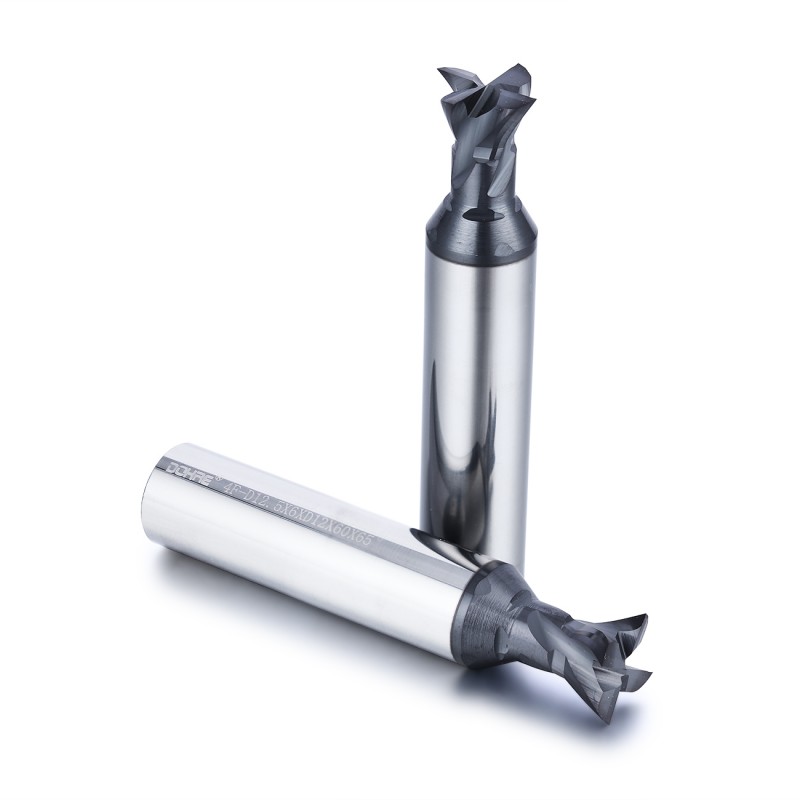
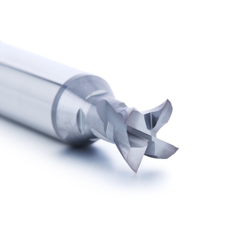
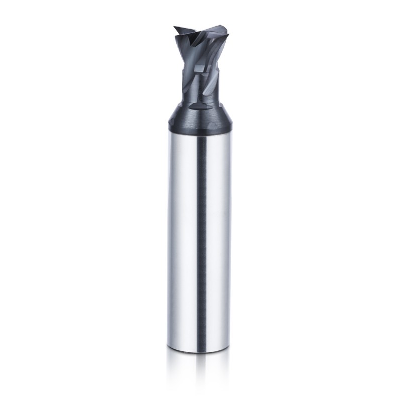
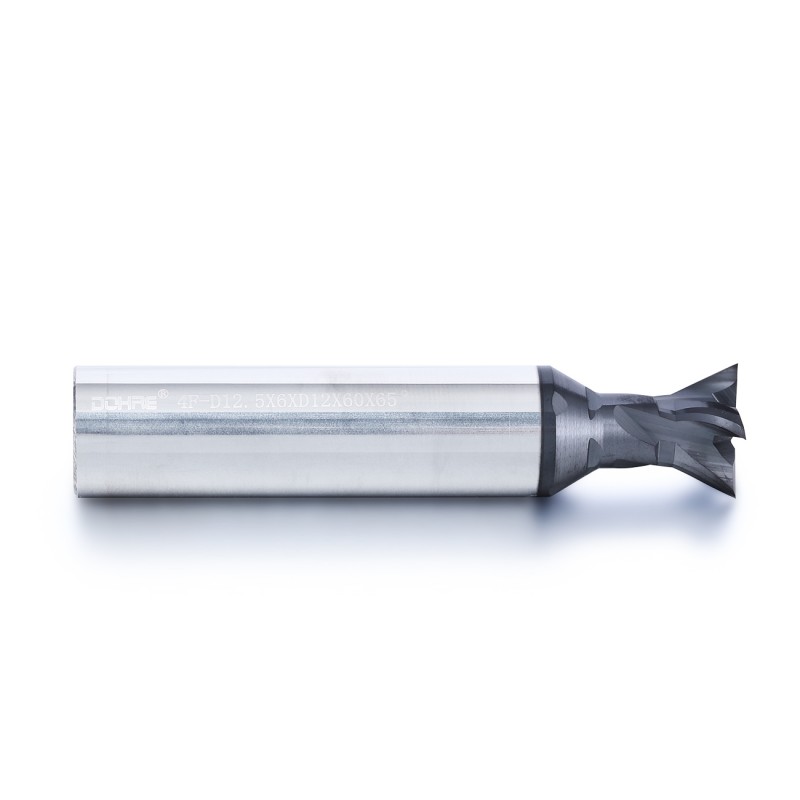
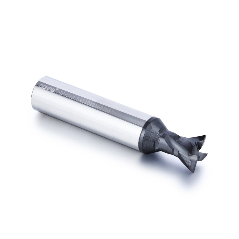
PCD Dovetail End Mill for Aluminum and Composites


PCD dovetail end mill designed for precision machining of dovetail grooves, undercuts, angled sidewalls and locking profiles in aluminum, high-silicon aluminum, graphite and composite materials.

  • PCD cutting edges for abrasive non-ferrous and composite materials
  • Custom dovetail angle, groove width and cutting diameter available
  • Reduced-neck geometry for undercut and recessed feature access
  • Drawing-based standard, prototype and OEM production available


Request a Quote

Description


Product Overview

This PCD dovetail end mill is designed for precision machining of dovetail grooves, undercuts, angled sidewalls and locking profiles in aluminum, high-silicon aluminum, graphite and composite materials.

The PCD cutting edges provide high wear resistance for abrasive non-ferrous and non-metallic materials, while the reduced-neck structure provides clearance for recessed and undercut features.

Dovetail angle, major diameter, minor diameter, groove width, neck diameter, neck length, cutting-edge quantity and overall dimensions can be customized according to the component drawing.

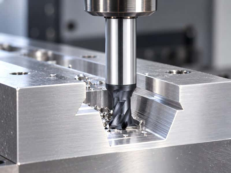
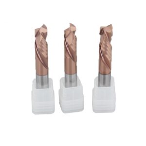
PCD dovetail end mill for aluminum and composite machining


Recommended Dovetail Machining Applications

Dovetail Grooves

Suitable for precision dovetail slots and locking grooves requiring controlled included angle and groove width.

Undercut Features

Reduced-neck geometry provides clearance for machining recessed undercuts and hidden side features.

Angled Sidewalls

Suitable for component features requiring a defined sidewall angle rather than a conventional straight slot.

Locking & Retaining Profiles

Custom profile geometry can be developed for locking, locating and retaining features used in precision components.


Why Use PCD for Dovetail Milling?

High Wear Resistance

PCD cutting edges are suited to abrasive aluminum alloys, graphite and composite materials where conventional carbide can wear more rapidly.

Stable Dovetail Angle

Strong edge retention helps maintain the specified dovetail angle during repeat and batch machining.

Consistent Groove Dimensions

Reduced cutting-edge wear supports more stable groove width and profile dimensions over longer production runs.

Repeat-Production Capability

PCD is well suited to applications where dimensional repeatability and extended production consistency are important.


PCD Dovetail Geometry & Access

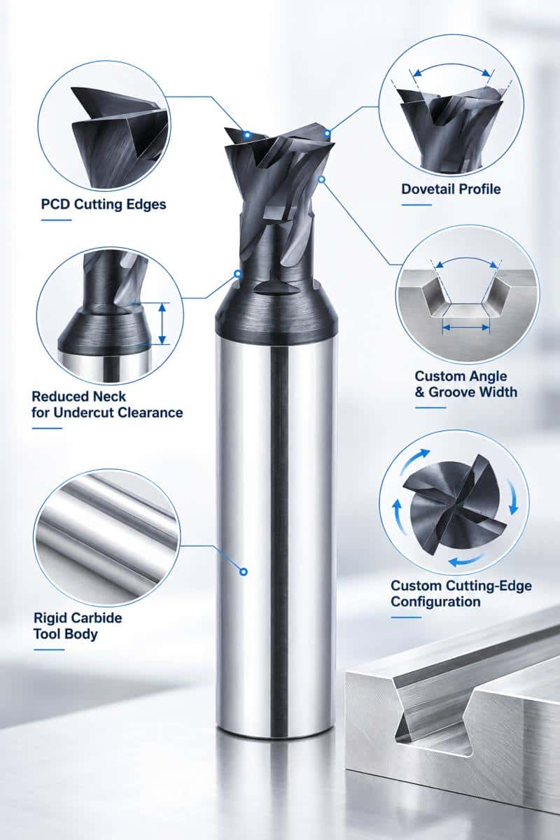
PCD dovetail end mill geometry and undercut clearance


PCD Cutting Edges

PCD cutting edges provide sharp, wear-resistant cutting performance for abrasive non-ferrous and composite materials.


Rigid Carbide Tool Body

The carbide body provides structural support for the PCD cutting section and helps maintain profile stability during side milling.


Drawing-Based Dovetail Profile

The cutting profile can be developed according to the required dovetail angle, groove dimensions and component geometry.


Custom Angle & Groove Width

Included angle, major diameter, minor diameter and axial cutting width can be customized for non-standard profiles.


Reduced Neck for Undercut Clearance

The reduced-neck section improves clearance around recessed features and prevents unnecessary tool-body interference.


Custom Cutting-Edge Configuration

Cutting-edge quantity and cutting direction can be selected according to workpiece material, groove geometry and machining method.


PCD Dovetail End Mill vs Carbide Dovetail Cutter


Attribute

PCD Dovetail End Mill

Carbide Dovetail Cutter
Best-Suited Materials Aluminum, high-silicon aluminum, graphite and abrasive composites General metals and broader material ranges depending on carbide grade
Wear Resistance Very high in suitable non-ferrous and non-metallic materials Application dependent
Production Focus High-repeatability and longer production runs General-purpose or lower-volume applications
Customization Drawing-based PCD profile and body geometry Standard and custom carbide geometry


Recommended Workpiece Materials

Aluminum & High-Silicon Aluminum

Well suited to aluminum and abrasive high-silicon aluminum components requiring stable groove geometry.

Graphite

PCD wear resistance is suitable for abrasive graphite applications requiring repeatable profile dimensions.

CFRP & GFRP

Suitable geometry can be developed for selected fiber-reinforced composite dovetail and undercut features.

Selected Non-Ferrous & Engineering Plastics

Suitable for selected non-ferrous metals and engineering plastics after review of geometry, chip evacuation and machining conditions.


Copper, magnesium and other non-ferrous materials should be evaluated according to profile geometry, cutting speed and chip-evacuation requirements.


Custom Configuration Options


PCD dovetail cutters can be developed according to the required groove profile, component access and production conditions.

Dovetail Included Angle Custom
Major Diameter Custom
Minor Diameter Custom
Groove / Cutting Width Custom
Neck Diameter Custom
Neck Length Custom
Shank Diameter Standard / Custom
Overall Length Custom
Cutting-Edge Quantity Application-Based
Cutting Direction Application-Based
OEM Service Laser Marking / Model Number / Private Label / Packaging


Recommended Dovetail Machining Setup

Prepare Access Where Required

Machine a pilot slot or clearance path first when the dovetail head cannot enter the final feature directly.

Check Neck & Holder Clearance

Verify neck, tool-body and holder clearance in CAM before machining recessed or undercut geometry.

Use Stable Side-Milling Engagement

Control radial engagement and avoid abrupt loading of the PCD cutting edges.

Control Tool Overhang

Use only the reach required by the component to reduce unnecessary deflection and vibration.

Maintain Chip Evacuation

Use air blast or another suitable method to keep chips and abrasive dust away from the cutting zone.

Verify Finished Profile

Check included angle, groove width and profile dimensions during initial setup before batch production.


Not every PCD dovetail cutter is center cutting. Confirm the actual end geometry before programming plunge entry.


From Component Drawing to Custom Dovetail Tool


Component geometry and machining conditions are reviewed together to confirm the required dovetail profile and tool clearance.


Component Information

  • 2D drawing or 3D model
  • Required dovetail angle
  • Major and minor groove dimensions
  • Groove width and depth
  • Workpiece material
  • Profile tolerance


Machining Information

  • Machine and spindle condition
  • Toolholder and runout
  • Available tool access
  • Required neck clearance
  • Chip evacuation method
  • Expected quantity


Custom Tool Development Process

STEP 01

Drawing Review

Review the dovetail feature, material and dimensional requirements.

STEP 02

Access Analysis

Evaluate entry path, neck clearance, holder clearance and surrounding geometry.

STEP 03

Profile Design

Develop the included angle, major diameter, minor diameter and cutting width.

STEP 04

Drawing Confirmation

Confirm the proposed cutter geometry before production.

STEP 05

Production & Inspection

Produce and inspect the initial cutter against the approved drawing.

STEP 06

Repeat Production

Support repeat-order, OEM and batch production after geometry confirmation.


Manufacturing & Quality Control


PCD Dovetail Tool Production


After the cutter drawing is confirmed, production follows the approved profile and dimensional requirements to support prototype, repeat-order, batch and OEM supply.

✓ Prototype production ✓ Drawing-controlled manufacturing
✓ Custom angle & profile production ✓ Batch consistency control
✓ Repeat-order production ✓ OEM laser marking & private label

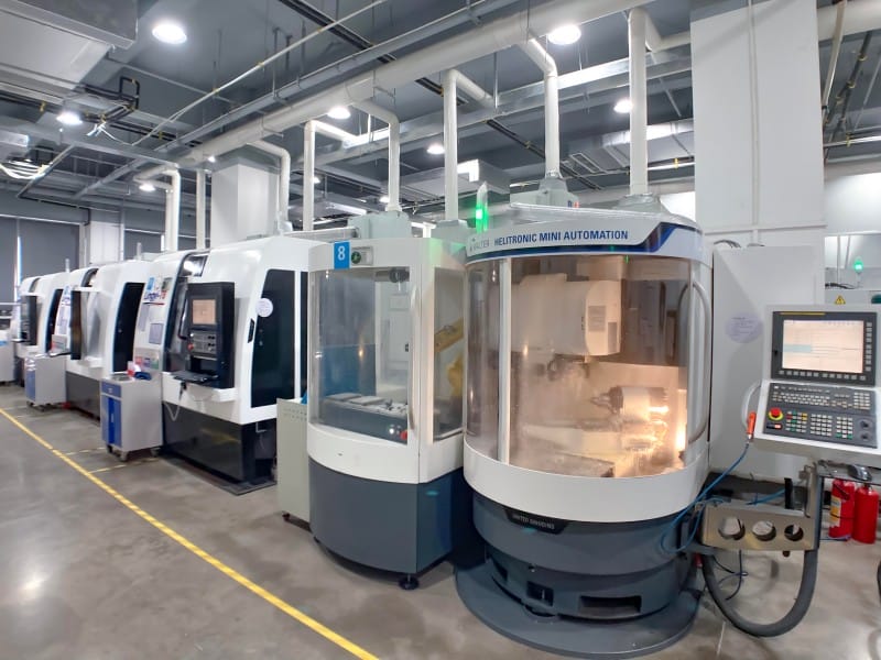
PCD dovetail end mill manufacturing at ZHY


Manufacturing Capability


EXPERIENCE

20+ Years

Cutting Tool Manufacturing


Experience in standard, custom and OEM cutting tools for industrial machining applications.


EQUIPMENT

Walter / ANCA / Deckel

Precision Manufacturing Equipment


Precision equipment supports controlled tool-body geometry and repeatable special-tool manufacturing.


CONTROL

Drawing-Controlled Production

Repeatable Custom Tool Geometry


Approved drawings and production records support consistent geometry for repeat and batch orders.


Inspection & Quality Control


Finished PCD dovetail end mills are inspected against the approved drawing, with focus on profile angle, major and minor diameter, groove width, neck clearance and PCD cutting-edge condition.

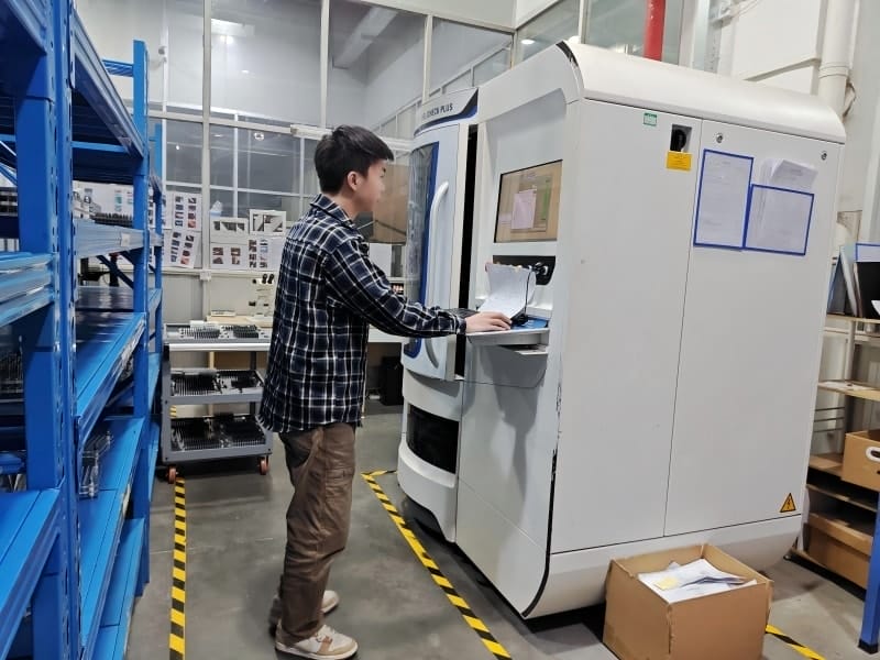
PCD dovetail end mill inspection and quality control


INSPECTION EQUIPMENT

HELICHECK PLUS

Profile & Dimensional Inspection


High-magnification inspection is used to evaluate profile geometry, critical dimensions and cutting-edge condition before shipment.

Included Angle & Profile

Dovetail angle and profile geometry are checked against the approved tool drawing.

Major & Minor Diameter

Critical diameters are inspected to support repeatable groove dimensions.

PCD Cutting Edge

PCD edge condition is inspected before final approval.

Batch Consistency

Inspection records support consistent geometry for repeat-order and OEM production.


PCD Dovetail End Mill FAQ


What is a PCD dovetail end mill used for?

It is used for precision dovetail grooves, undercuts, angled sidewalls and locking profiles in suitable non-ferrous and composite materials.


Can the dovetail angle be customized?

Yes. Included angle, major diameter, minor diameter, groove width, neck dimensions and overall tool geometry can be developed according to the component drawing.


Is PCD suitable for aluminum?

Yes. PCD is particularly suitable for aluminum and high-silicon aluminum applications where high wear resistance and long dimensional stability are required.


Can a PCD dovetail cutter be reground?

Regrinding feasibility depends on the remaining PCD layer, cutter geometry and edge condition. The tool should be evaluated before regrinding.
Need a Custom PCD Dovetail End Mill?

Send us your component drawing, workpiece material, dovetail angle, groove dimensions and access conditions. We can evaluate the suitable PCD profile and tool configuration.


Request a Custom Tool Quote   →