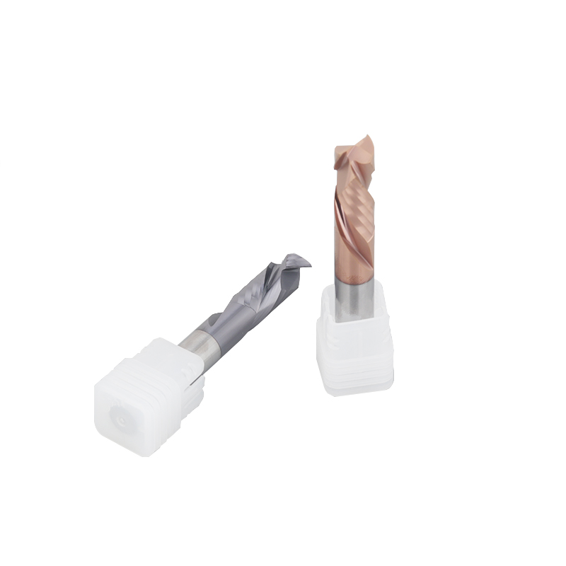
Description
Product Overview
This solid carbide compression end mill is designed
for profile milling, edge trimming, slotting and
cutout machining of laminated panels, plywood, MDF,
engineering plastics and selected composite materials.
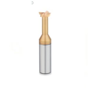
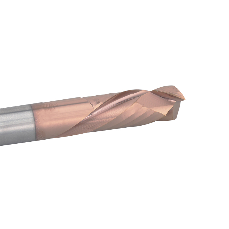
The cutting section combines opposite helix directions.
A typical compression design uses an upcut section near
the tool tip and a downcut section above it, directing
cutting forces toward the center of the workpiece.
This helps improve edge quality on both the upper and
lower surfaces during through-cutting operations.
Recommended Compression Milling Applications
Compression end mills are intended primarily for
through-cutting and edge-machining applications where
both the top and bottom surfaces require controlled
edge quality.
Panel Profile Cutting
Suitable for external profiles and component
outlines in laminated boards, plywood,
plastics and composite panels.
Edge Trimming
Opposite helix directions help control fraying,
breakout and chipping along the upper and
lower workpiece edges.
Through Slotting
Suitable for full-depth slots when both flute
sections are correctly engaged and chip
evacuation is properly controlled.
Windows and Cutouts
Can be used for internal openings, windows,
access holes and other through-cut features
in panels and formed components.
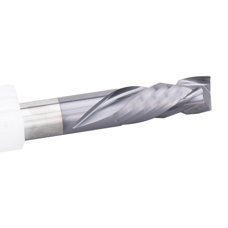
How Compression Cutting Geometry Works
The upper and lower sections of the cutter use opposite
helix directions. Their cutting forces act toward the
center of the workpiece rather than pulling both surfaces
in the same direction.
Lower Upcut Section
- Normally positioned near the tool tip
- Directs chips and cutting force upward
- Helps support the lower workpiece edge
- Reduces breakout on the bottom surface
- Requires sufficient engagement below the panel
- Upcut length should match the panel thickness and toolpath
Upper Downcut Section
- Normally positioned above the upcut section
- Directs cutting force downward
- Helps hold the upper surface fibers or laminate in place
- Reduces top-edge fraying and lifting
- Should engage the upper surface during final-depth cutting
- Downcut length can be customized for the application
Why Cutting Depth Is Important
The compression effect is only achieved when the cutting
depth positions the transition between the two helix
sections inside the workpiece thickness.
Correct Engagement
- The lower surface is cut by the upcut section
- The upper surface is cut by the downcut section
- The helix transition remains inside the panel
- Cutting forces act toward the material center
- Both surfaces receive the intended compression effect
- Panel thickness should be confirmed before tool selection
Incorrect Engagement
- Shallow cutting may use only the upcut section
- Incorrect depth may leave the top surface uncompressed
- Excessive depth can increase tool overhang and load
- The helix transition may be positioned outside the material
- Edge quality may vary between the upper and lower surfaces
- The actual tool drawing should be used for programming
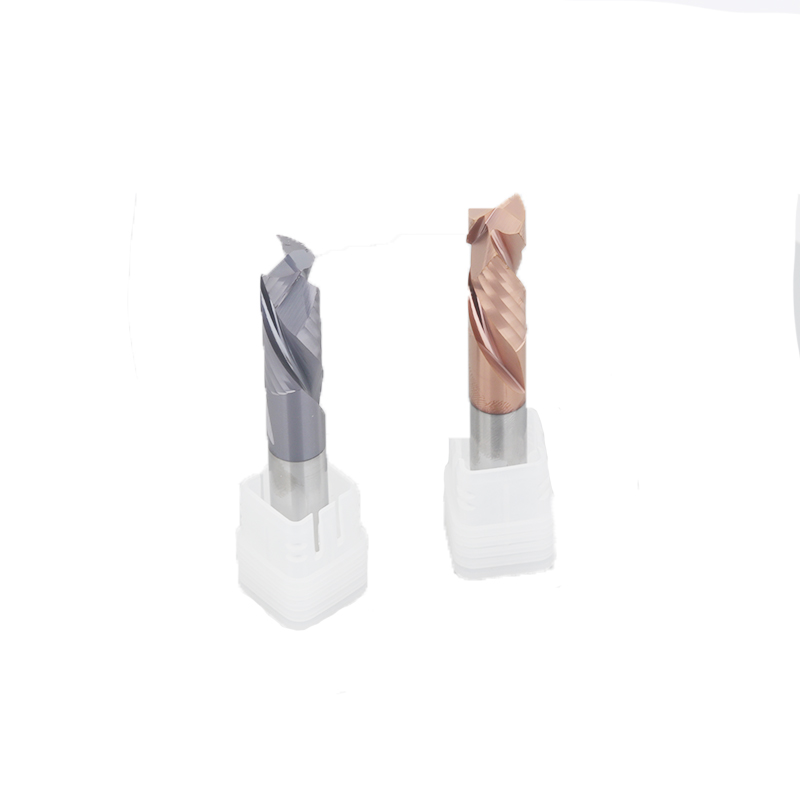
Compression End Mill vs Upcut and Downcut End Mills
The correct flute direction depends on the required
surface quality, chip evacuation and workpiece structure.
Compression End Mill
Combines opposite helix sections to direct cutting
forces toward the center and improve both top
and bottom edge quality.
Upcut End Mill
Provides effective upward chip evacuation but
may lift fibers or laminate on the upper
workpiece surface.
Downcut End Mill
Helps control the upper surface but directs
chips downward and may require additional
chip-clearance consideration.
Selection Principle
Use a compression cutter when both surfaces
require controlled edge quality and the machining
depth can engage both flute directions.
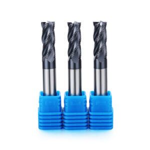
Compression End Mill Design and Performance
Upcut length, downcut length, flute transition,
cutting diameter, tool reach and cutting-edge geometry
are selected together according to the panel thickness,
material and machining process.
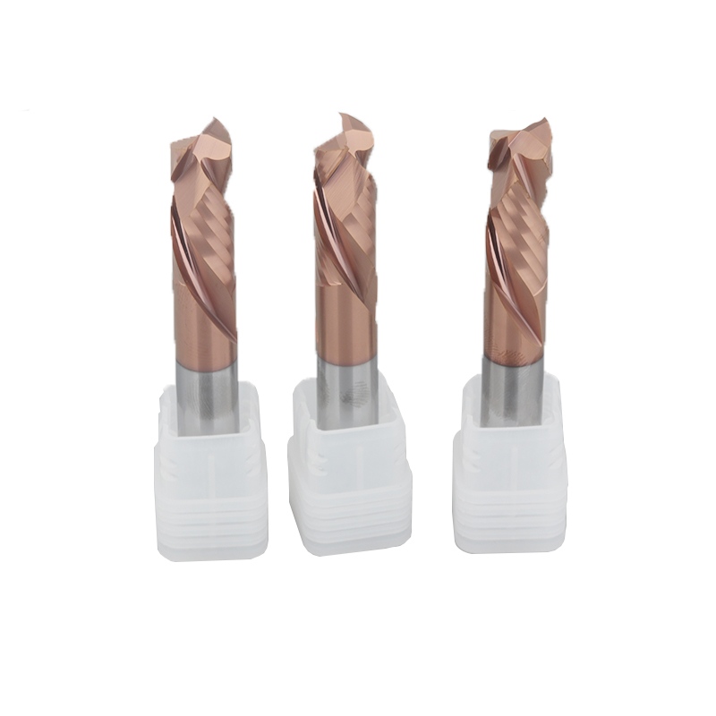
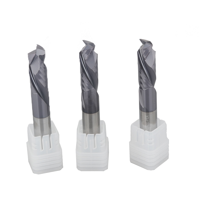
Solid Carbide Construction
Solid carbide provides rigidity, dimensional
stability and wear resistance for panel,
plastic and composite machining.
Opposite Helix Directions
Upcut and downcut flute sections create opposing
axial cutting forces across the workpiece thickness.
Controlled Upper Edge
The downcut section helps limit lifting,
fraying and chipping along the upper
workpiece surface.
Controlled Lower Edge
The upcut section helps support the lower
workpiece edge and reduce breakout during
through-cutting operations.
Reduced Laminate Separation
Center-directed cutting forces can help reduce
separation between surface layers and
the main panel structure.
Through-Cutting Capability
The tool is especially suitable for full-depth
profile, slot and cutout machining where
both surfaces are exposed.
Custom Upcut Length
The lower flute-section length can be adjusted
according to panel thickness, cutting depth
and bottom-edge requirements.
Custom Downcut Length
The upper flute section can be designed according
to the required top-surface engagement and
total cutting length.
Controlled Flute Transition
The position where the opposing helix sections
meet is selected according to the workpiece
thickness and machining depth.
Custom End Geometry
End cutting, center-cutting capability and
entry geometry can be reviewed according to
the required cutting strategy.
Application-Specific Coating
Uncoated or wear-resistant coating options can
be selected according to the actual workpiece
material and abrasiveness.
Drawing-Based Customization
Cutting diameter, flute-section lengths,
shank diameter and overall length can be
manufactured according to customer requirements.
Recommended Workpiece Materials
Material compatibility should be confirmed according
to the panel structure, fiber or filler content,
surface laminate, abrasiveness and required edge quality.
CFRP, GFRP, honeycomb sandwich panels and other
highly abrasive composites should be reviewed
separately before selecting the carbide grade,
cutting geometry and coating.
Available Compression End Mill Configurations
Final tool dimensions should be selected according
to material type, panel thickness, cutting depth,
spindle conditions and required edge quality.
| Tool Type | Solid Carbide Compression End Mill |
|---|---|
| Alternative Names | Compression Router Bit / Upcut and Downcut End Mill / Opposite-Helix End Mill |
| Tool Material | Solid Carbide |
| Cutting Geometry | Opposite Upcut and Downcut Helix Sections |
| Cutting Diameter | Standard or Customized |
| Upcut Length | Selected According to Panel Thickness and Cutting Depth |
| Downcut Length | Standard or Customized |
| Total Cutting Length | Standard / Extended / Drawing-Based Custom Length |
| Shank Diameter | Standard or Customized |
| Overall Length | Standard or Customized |
| End-Cutting Capability | Must Be Confirmed According to Selected Tool Geometry |
| Main Operations | Profile Milling / Edge Trimming / Through Slotting / Cutout Machining |
| Coating | Uncoated or Application-Specific Wear-Resistant Coating |
| Custom Options | Diameter / Upcut Length / Downcut Length / Cutting Length / Shank / Overall Length / End Geometry |
| OEM Options | Laser Marking / Customer Model Number / Custom Label / Private-Label Packaging |
Please provide the material type, panel thickness,
cutting depth, required diameter, cutting length,
shank diameter and machine information before
confirming the compression flute configuration.
Compression End Mill Selection Guidelines
The most important selection point is the relationship
between panel thickness, cutting depth and the transition
position between the upcut and downcut sections.
Confirm the Workpiece
- Material type and panel construction
- Panel thickness
- Surface laminate or coating
- Fiber or filler content
- Required top and bottom edge quality
- Through cut, slot or profile operation
Confirm the Tool Dimensions
- Required cutting diameter
- Required upcut flute length
- Required total cutting length
- Shank diameter and holder type
- Overall length and effective overhang
- Available clearance below the workpiece
Recommended Machining Method
Edge quality and tool life depend on correct cutting
depth, stable workholding, controlled runout,
suitable feed and effective chip or dust evacuation.
Recommended Setup
- Use stable panel support and workholding
- Use a low-runout collet and toolholder
- Confirm the flute transition position before programming
- Cut deeply enough to engage both helix directions
- Provide effective dust and chip extraction
- Inspect both surfaces before batch production
Conditions Requiring Attention
- Cutting depth engages only one flute direction
- Panel movement or vibration during machining
- Insufficient clearance below the workpiece
- Excessive tool overhang
- Poor dust evacuation or chip recutting
- Incorrect geometry for the material structure
Entry and Toolpath Considerations
Not every compression end mill has the same end-cutting
or plunging capability. The entry method should match
the actual cutting-end geometry.
Recommended Entry Methods
- Use an external edge entry when possible
- Use a pre-drilled entry hole when required
- Apply a ramp or helical entry only if geometry permits
- Avoid sudden full-diameter engagement
- Maintain continuous feed around the profile
- Use a verified lead-in and lead-out path
Toolpath Verification
- Confirm the final cutting depth
- Check the transition position inside the panel
- Verify toolholder and shank clearance
- Check the cutter path at internal corners
- Confirm waste-part support before breakthrough
- Simulate restricted or complex profiles
Custom Compression End Mill Options
Non-standard compression cutters can be developed
according to panel thickness, workpiece material,
machining depth, required edge quality and machine setup.
Information Required for Tool Selection
Complete material and machining information helps
determine the correct upcut length, downcut length,
flute transition and tool dimensions.
Workpiece Information
- Material type and exact panel structure
- Panel thickness
- Surface laminate or coating
- Top and bottom edge requirements
- Profile, slot or cutout drawing
- Production quantity
Machining Information
- Machine and spindle type
- Maximum spindle speed
- Toolholder and shank diameter
- Required cutting depth
- Dust or chip extraction method
- Current tool and cutting parameters
Custom Compression Tool Development Process
Custom flute geometry is developed according to
material structure, panel thickness, tool engagement
and required double-sided edge quality.
Solid Carbide Compression End Mill Manufacturer
ZHY supplies standard and drawing-based compression
end mills to panel manufacturers, woodworking companies,
plastic machining suppliers, composite processors,
distributors and private-label cutting-tool brands.
Application and Production Support
- Material and panel-thickness review
- Custom upcut and downcut flute sections
- Standard and extended cutting lengths
- Application-specific carbide and coating selection
- Prototype tools for edge-quality verification
- Standard and custom batch production
OEM and Private Label
- Customer logo laser marking
- Customer model and product numbers
- Custom labels and barcode stickers
- Plastic box and outer-carton options
- Private-label packaging support
- Packaging verification before shipment
Production and Quality Inspection
Cutting diameter, upcut and downcut flute geometry,
transition position, cutting length and cutting-edge
appearance are inspected before delivery.
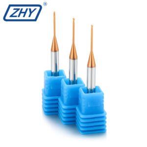
Explore More Custom End Mills
View additional special-purpose and drawing-based
carbide cutters for panel, plastic and
composite component machining.
Request a Compression End Mill Recommendation
Send us the material type, panel thickness, required
top and bottom edge quality, cutting diameter,
cutting depth, upcut length, total cutting length,
shank diameter, machine information and order quantity.
Our team will review the application and recommend a
suitable standard or custom solid carbide compression end mill.