Description
Product Overview
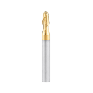
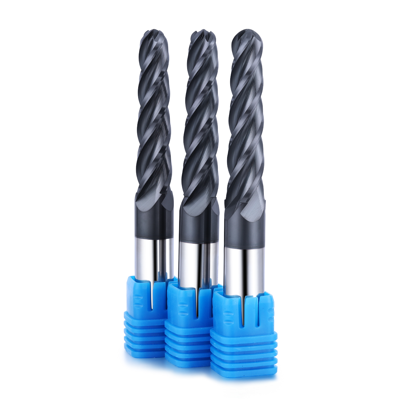
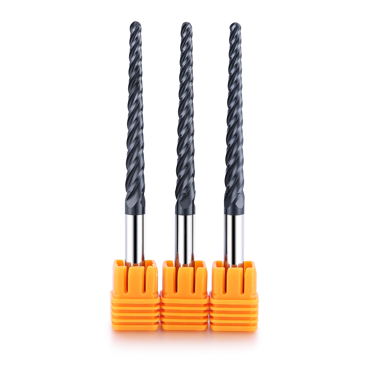
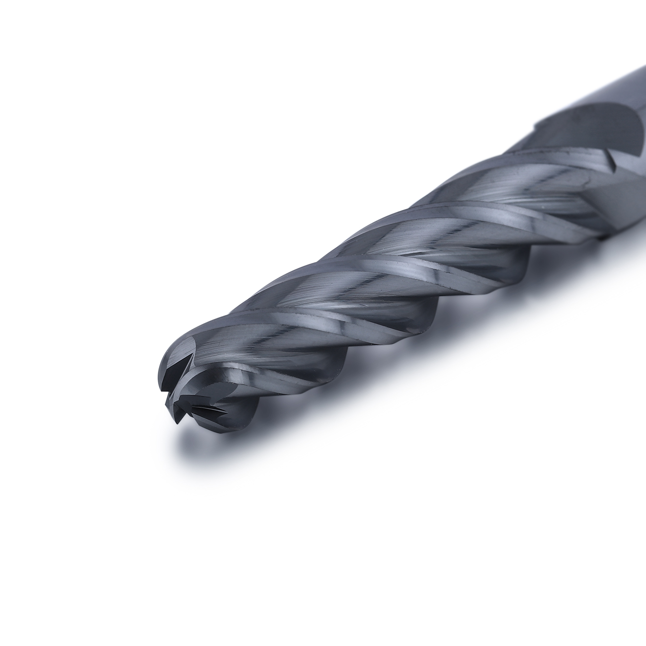
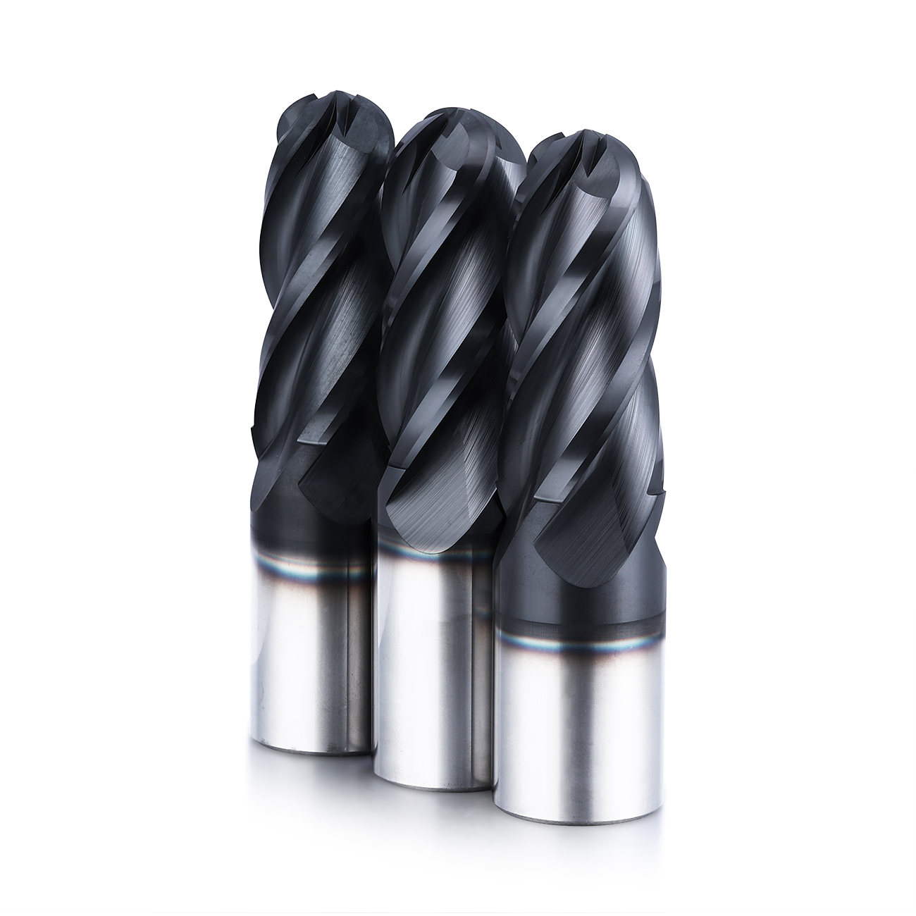
This custom tapered ball nose end mill is developed for
continuous machining of aircraft wing components,
contoured structural surfaces, tapered walls and long
three-dimensional toolpaths.
Aircraft wing machining may require one cutter to complete
the entire programmed machining cycle without an unplanned
tool change or mid-process breakage. To improve complete-cycle
reliability, a precision laser-machined micro-groove is formed
beneath the helical cutting section of the tool.
Recommended Aircraft Wing Machining Applications
This tool is intended for aerospace component applications
requiring tapered geometry, ball nose contouring capability,
extended reach and reliable performance over long continuous
machining cycles.
Aircraft Wing Profiles
Suitable for continuous contour machining of
aircraft wing components and complex
three-dimensional structural profiles.
Tapered Wall Machining
The tapered tool structure supports inclined walls,
tapered cavities and component features requiring
controlled angular geometry.
Continuous Contour Milling
Designed for long programmed toolpaths where
machining interruption and unexpected cutter
breakage must be minimized.
Deep and Recessed Features
Custom taper, neck and overall length configurations
provide access to deeper or partially recessed
aircraft structural features.
Why Complete-Cycle Reliability Matters
Aircraft wing machining can involve long machining times,
continuous contour transitions and extended tool engagement.
An unexpected tool breakage during the programmed cycle can
interrupt production and require the component, toolpath
and machining setup to be checked again.
Continuous Machining Requirement
- One cutter is expected to complete the scheduled cycle
- Unplanned tool changes should be minimized
- Cutting performance must remain stable over long toolpaths
- Tapered walls and contours require consistent geometry
- Tool wear should remain predictable during production
- The cutter must match the actual CAM machining strategy
Risks of Mid-Cycle Tool Failure
- Unexpected interruption of the machining cycle
- Additional component and machine inspection
- Re-establishment of the tool and machining position
- Possible marks at the interrupted machining area
- Reduced production continuity
- Higher uncertainty in long-cycle aerospace machining
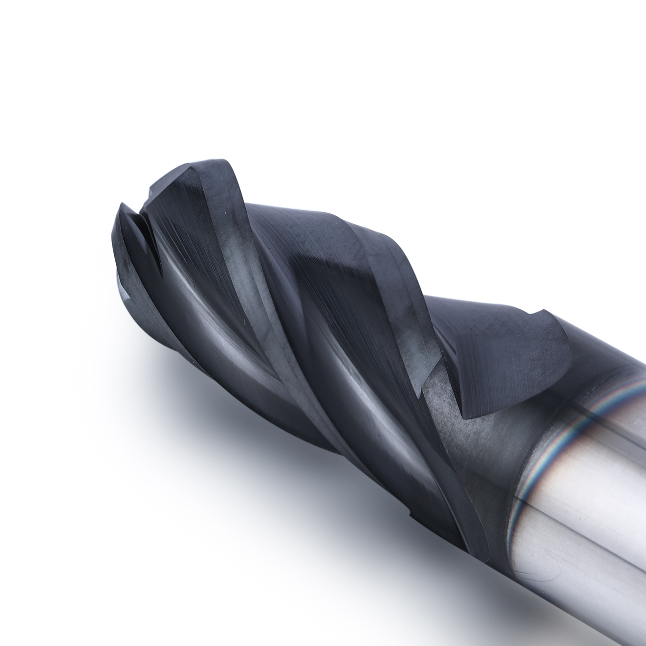
Laser-Machined Micro-Groove Technology
A precision micro-groove is produced by laser beneath
the helical cutting section. This application-specific
feature is designed to improve local stress behavior and
enhance tool-life stability during long continuous machining.
Micro-Groove Design
- Produced by precision laser processing
- Located beneath the helical cutting section
- Small and controlled groove geometry
- Position developed according to the tool structure
- Does not replace the primary cutting flute geometry
- Applied as part of the complete custom tool design
Design Objective
- Improve local stress distribution
- Reduce the risk of sudden mid-cycle breakage
- Support longer continuous machining cycles
- Improve usable tool-life stability
- Increase the probability of completing the full component
- Support repeatable aircraft wing production
Application-Verified Tool-Life Improvement
The laser micro-groove design has been evaluated in an
actual aircraft wing machining application. The following
figures refer to that specific application and should not
be treated as a universal tool-life guarantee.
| Performance Item | Previous Tool Design | Laser Micro-Groove Design |
|---|---|---|
| Average Completed Wing Components per Tool | Approximately 2.5 Components | Approximately 3 Components |
| Tool Design | Original Tapered Ball Nose Geometry | Tapered Ball Nose Geometry with Laser-Machined Micro-Groove |
| Main Improvement Target | Standard Continuous Machining | Improved Complete-Cycle Reliability and Tool-Life Stability |
The above result comes from a specific customer
application. Actual tool life depends on workpiece
material, component geometry, cutting parameters,
toolpath, tool overhang, spindle runout, machine rigidity
and coolant or lubrication conditions.
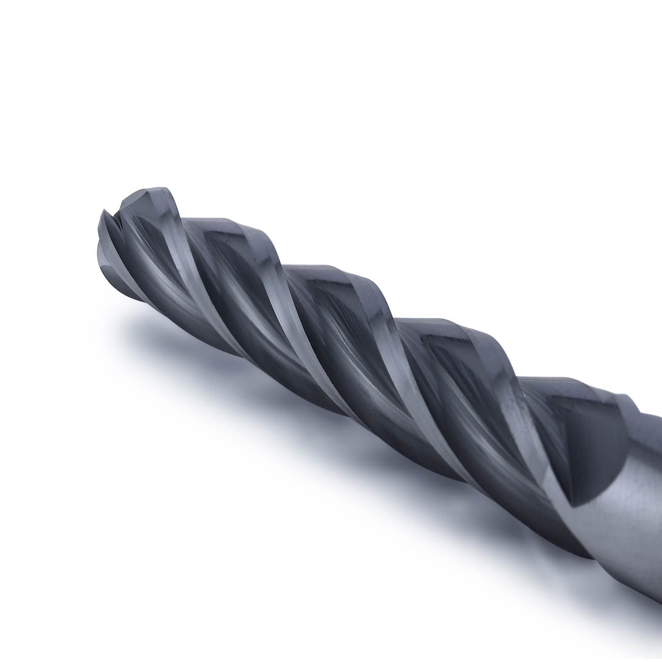
How the Tapered Ball Nose Geometry Works
The tapered body and ball nose profile provide different
functions. The tapered section supports tool rigidity and
inclined-wall access, while the ball nose supports smooth
contour transitions and three-dimensional surface machining.
Tapered Tool Structure
- Supports inclined and tapered component walls
- Provides a stronger section than a fully reduced neck
- Can improve rigidity in extended-reach applications
- Taper angle can match the component profile
- Helps control interference in deep structures
- Must be verified against the full toolpath
Ball Nose Cutting Profile
- Suitable for three-dimensional contour machining
- Supports curved and transitional surfaces
- Provides controlled contact on complex profiles
- Ball radius can be customized to the component
- Suitable for semi-finishing and finishing toolpaths
- Tool tilt and contact point affect actual cutting speed
Aircraft Wing End Mill Design and Performance
Tool material, tapered geometry, ball radius, laser
micro-groove position, flute design and overall reach are
developed together according to the aircraft component
drawing and machining process.
Solid Carbide Construction
Solid carbide construction provides the rigidity,
dimensional stability and wear resistance required
for long continuous machining cycles.
Tapered Tool Geometry
The tapered structure supports inclined-wall
machining while maintaining tool strength and
clearance in deep component features.
Ball Nose Profile
The ball nose supports curved surfaces,
three-dimensional contours and smooth transitions
across aircraft structural profiles.
Laser Micro-Groove
A controlled laser-machined groove beneath the
helical section is incorporated to improve
tool-life stability in the verified application.
Complete-Cycle Reliability
The tool is developed to complete long aircraft
wing machining cycles without an unplanned
mid-process tool change.
Reduced Breakage Risk
Tool geometry and laser processing are designed
together to reduce the risk of unexpected breakage
during controlled continuous machining.
Stable Tool Core
The tapered carbide body provides support against
bending and deflection during extended-reach
aircraft component machining.
Long Continuous Toolpaths
The tool is developed for applications involving
long contour paths and extended periods of
continuous cutting engagement.
Custom Taper Angle
Taper angle can be developed according to the
aircraft component wall angle, access requirement
and CAM toolpath.
Custom Ball Radius
Ball radius can be matched to the component contour,
transition radius and required surface condition.
Application-Specific Coating
Carbide grade and coating can be selected according
to the actual aircraft component material,
cutting speed and coolant condition.
Drawing-Based Customization
Cutting diameter, taper angle, ball radius,
cutting length, shank and overall length can be
manufactured according to the customer drawing.
Recommended Component Features
The exact workpiece material and cutting configuration
should be confirmed from the aircraft component drawing,
alloy grade and approved machining process.
Do not select the carbide grade or coating only from
the general description “aircraft wing.” Please provide
the exact workpiece alloy, hardness or material condition
before tool production.
Available Tapered Ball Nose End Mill Configurations
This is an application-specific custom tool. Final dimensions
should be confirmed according to the aircraft component
drawing, toolpath, holder and machine conditions.
| Tool Type | Tapered Ball Nose End Mill |
|---|---|
| Primary Application | Aircraft Wing Component Machining |
| Tool Material | Solid Carbide |
| Standard Flute Configuration | Current Product Configuration: 4 Flutes |
| Special Technology | Laser-Machined Micro-Groove Beneath the Helical Cutting Section |
| Cutting Diameter | Drawing-Based Custom Diameter |
| Ball Radius | Custom According to Component Profile |
| Taper Angle | Custom According to Wall Angle and Access |
| Cutting Length | Application-Specific Custom Length |
| Neck Length | Standard / Extended Reach / Custom |
| Shank Diameter | Standard or Custom Shank |
| Overall Length | Drawing-Based Custom Length |
| Coating | Selected According to Workpiece Alloy, Cutting Speed and Coolant Condition |
| Main Operations | Continuous Contour Milling / Tapered Wall Machining / Profile Milling / Deep-Reach Machining |
| OEM Options | Custom Geometry / Laser Marking / Customer Model Number / Private Label |
Send us the component drawing, taper angle,
ball radius, cutting diameter, cutting length,
tool reach, shank diameter, overall length,
workpiece material and CAM toolpath information
for technical evaluation.
Recommended Continuous Machining Conditions
Tool-life stability depends on the complete machining system.
The cutter should be used with rigid workholding,
controlled runout and a verified continuous toolpath.
Recommended Setup
- Use a rigid machine and stable workholding system
- Use a low-runout spindle and toolholder
- Keep the effective tool overhang under control
- Use a verified continuous machining toolpath
- Maintain stable chip evacuation and cooling
- Inspect tool wear before the full wing cycle
Conditions Requiring Review
- Excessive tool overhang
- Sudden changes in radial engagement
- High spindle or holder runout
- Unexpected machine vibration
- Incorrect coating for the workpiece alloy
- Toolpath transitions that create impact loading
Custom Aircraft Wing Milling Tool Options
The tool can be developed according to the aircraft
component drawing, wall angle, contour, machining depth,
cycle time and existing tool-life requirement.
Information Required for Tool Development
Complete component and machining information is required
to evaluate taper interference, tool strength, cutting
engagement and complete-cycle reliability.
Component Information
- 2D drawing or 3D component model
- Exact workpiece material and condition
- Tapered wall angle and contour radius
- Machining depth and accessibility
- Dimensional and surface requirements
- Number of components required per tool
Machining Information
- Machine type and spindle interface
- Current spindle speed and feed rate
- Toolholder type and measured runout
- Effective tool overhang
- Coolant or lubrication method
- Current tool life and breakage position
Custom Tool Development Process
The tapered ball nose geometry and laser micro-groove
are developed according to the component and verified
through dimensional and application evaluation.
Custom Aircraft Wing Milling Cutter Manufacturer
ZHY supplies drawing-based tapered ball nose end mills
to aerospace component manufacturers, precision machining
companies, cutting-tool distributors and private-label brands.
Application and Production Support
- Aircraft component drawing review
- Existing tool failure and life analysis
- Custom taper, radius and reach design
- Laser micro-groove processing
- Prototype tools for machining verification
- Batch production after application confirmation
OEM and Private Label
- Customer logo laser marking
- Customer model and product numbers
- Custom labels and barcode stickers
- Application-specific packaging
- Private-label production support
- Packaging verification before shipment
Production and Quality Inspection
Carbide material, taper angle, ball radius, flute geometry,
laser micro-groove position and final cutting-edge condition
are inspected before delivery.
Explore More Custom End Mills
View additional custom-profile and special-purpose
milling cutters for complex component machining.
Request an Aircraft Wing End Mill Recommendation
Send us the aircraft component drawing, workpiece material,
taper angle, ball radius, machining depth, tool overhang,
current cutting parameters, tool-breakage position,
existing tool life and required production quantity.
Our team will review the application and develop a suitable
tapered ball nose end mill with an application-specific
laser micro-groove design.