Description
Product Overview
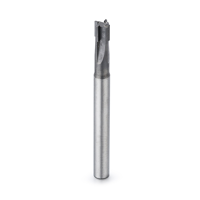
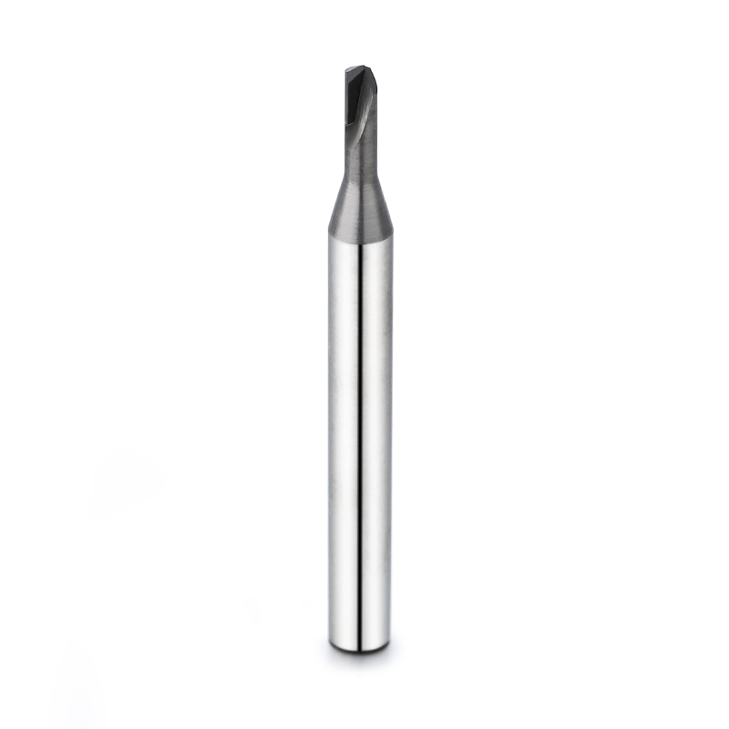
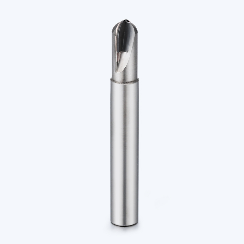
This custom PCD form milling cutter is developed for profile
machining, stepped features, special grooves, undercuts,
recessed surfaces and combined machining operations in
aluminum, graphite, composites and other abrasive
non-ferrous or non-metallic materials.
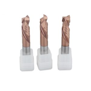
The tool combines a rigid carbide body with application-specific
PCD cutting edges. Multiple diameters, steps, angles, grooves
and transition features can be integrated into one tool
according to the component drawing and machining process.
Recommended Machining Applications
Custom PCD form cutters are suitable when a standard end mill
cannot complete the required contour efficiently or when
several features need to be machined in one operation.
Profile Milling
Custom cutting profiles can reproduce component
contours, radii, angular surfaces and application-specific
edge geometries.
Step and Shoulder Machining
Multiple cutting diameters and axial positions can
be combined for stepped surfaces, shoulders and
diameter transitions.
Slot and Undercut Machining
Application-specific cutting heads can be developed
for internal grooves, recessed features, T-slots
and undercut profiles.
Combined Feature Machining
Several component features can be machined with
one customized cutter to reduce tool changes,
positioning steps and cycle time.
Why Use a Custom PCD Form Milling Cutter?
Standard tools often require several machining operations
to complete a complex profile. A drawing-based form cutter
can combine those features into one controlled cutting geometry.
Integrated Machining Efficiency
- Combines several cutting features in one tool
- Reduces tool-change frequency
- Reduces repeated positioning operations
- Supports shorter machining cycles
- Suitable for repeated production parts
- Can simplify CNC programming and process planning
Profile and Dimensional Consistency
- Geometry developed from the component drawing
- Stable relationship between combined features
- PCD edge retention supports repeatable profiles
- Suitable for automated batch production
- Helps reduce variation between tool changes
- Final geometry can be inspected before delivery
Custom PCD Tool Design and Cutting Performance
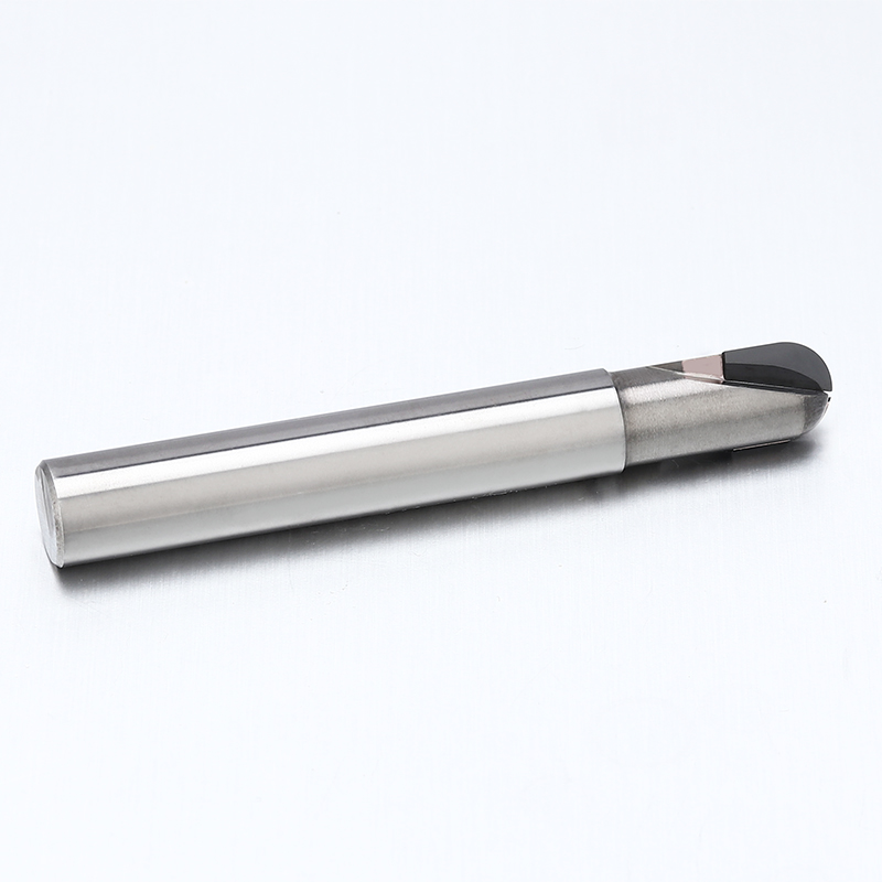
The PCD cutting edges, rigid tool body and application-specific
profile are designed together according to the workpiece
material, component geometry and production requirements.
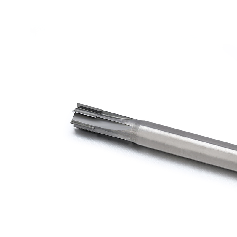
PCD Cutting Edges
Polycrystalline diamond cutting edges provide high
abrasion resistance for aluminum, graphite,
composites and other abrasive materials.
Rigid Carbide Tool Body
The carbide body provides structural support for
the PCD cutting sections and helps maintain stable
tool positioning during profile machining.
Drawing-Based Cutting Profile
The cutting geometry can be developed according
to the required component profile, dimensions,
radii and angular features.
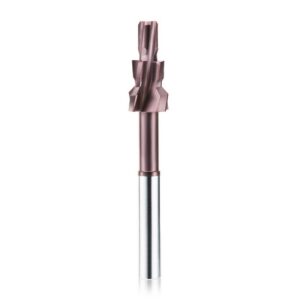
Multi-Step Geometry
Multiple diameters and axial cutting positions
can be integrated for stepped surfaces,
shoulders and combined features.
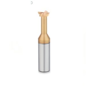
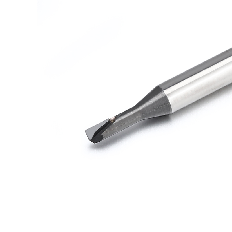
Slot and Undercut Capability
Special head profiles can be designed for grooves,
recessed surfaces, undercuts and other features
that standard end mills cannot easily reach.
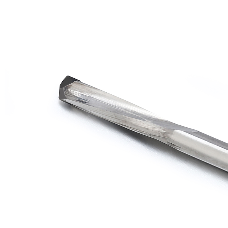
Sharp Cutting Geometry
Precision-ground PCD cutting edges support clean
shearing, low cutting resistance and controlled
burr formation in suitable materials.
High Wear Resistance
PCD resists abrasive wear caused by silicon particles,
graphite, carbon fibers and glass-fiber reinforcement.
Long Cutting-Edge Retention
Stable edge geometry supports longer machining
cycles and helps reduce the frequency of tool
replacement in batch production.
Custom Cutting-Edge Quantity
The number and position of PCD cutting edges can
be selected according to chip space, feed capability,
profile width and productivity requirements.
Custom Cutting Direction
Right-hand or left-hand cutting configurations
can be developed where required by the machine,
spindle direction or component setup.
Custom Neck and Reach
Neck diameter, neck length, cutting position and
overall reach can be adjusted for recessed or
difficult-to-access component features.
Regrinding Evaluation
Selected PCD form cutters can be inspected for
regrinding or repair depending on cutting-edge
wear, remaining material and tool construction.
Typical Custom Tool Profiles
The final tool structure depends on the component drawing
and machining sequence. The following profiles represent
common custom design directions.
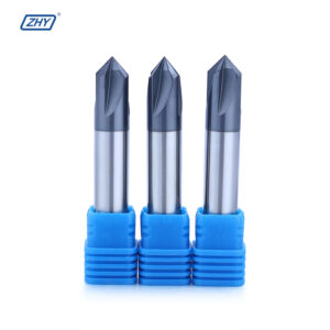
Profile and Step Cutters
- Single-step and multi-step profiles
- Combined diameter transitions
- Shoulder and contour machining
- Custom radii and angular surfaces
- External profile finishing
- Multiple features machined in one pass
Slot and Undercut Cutters
- Internal groove machining
- T-slot-type component features
- Undercut and recessed profiles
- Back-side edge machining
- Special cutting-head diameters
- Custom cutting width and neck clearance
Recommended Workpiece Materials
Custom PCD form milling cutters are primarily intended
for non-ferrous metals, composites, graphite and abrasive
non-metallic materials.
Available Custom PCD Cutter Configurations
Each tool can be developed according to the component
drawing, machining sequence, machine interface and
required production volume.
| Tool Type | Custom PCD Form Milling Cutter |
|---|---|
| Cutting Material | PCD Cutting Edges |
| Tool Body | Carbide Tool Body |
| Cutting Profile | Profile / Step / Slot / Undercut / Groove / Combined Geometry |
| Tool Diameter | Drawing-Based Custom Diameter |
| Cutting Width | Custom According to Component Feature |
| Step Dimensions | Single Step / Multiple Steps / Custom |
| Neck Diameter | Standard / Reduced Neck / Custom Clearance |
| Neck Length | Standard / Long Reach / Custom |
| Cutting-Edge Quantity | According to Tool Design and Application |
| Cutting Direction | Right-Hand / Left-Hand Where Applicable |
| Internal Coolant | Available Where Tool Structure Permits |
| Main Operations | Profile Milling / Step Machining / Slotting / Undercutting / Combined Feature Machining |
| OEM Options | Custom Geometry / Laser Marking / Customer Model Number / Private Label |
Send us the component drawing, workpiece material,
profile dimensions, tool diameter, cutting width,
step dimensions, neck requirements, machine interface
and annual production quantity for tool evaluation.
Information Required for Custom Tool Design
Complete component and machining information helps confirm
the cutting profile, tool accessibility and production feasibility.
Component Information
- 2D drawing or 3D component model
- Workpiece material and exact grade
- Required machined profile
- Dimensional tolerances
- Surface-quality requirements
- Interference and accessibility limitations
Machining Information
- Machine type and spindle interface
- Spindle rotation direction
- Available spindle speed and feed
- Toolholder and runout condition
- Cooling, lubrication or air-blast method
- Expected production quantity
Custom PCD Tool Development Process
The tool is developed from the component feature and
machining process rather than from a standard catalogue size.
Custom PCD Form Milling Cutter Manufacturer
ZHY supplies drawing-based PCD form cutters to component
manufacturers, machining companies, cutting-tool distributors
and private-label tool brands.
Application and Production Support
- Component drawing and process review
- Profile, step, groove and undercut designs
- Prototype tools for machining verification
- Standard and long-reach tool bodies
- Mixed-model and batch-order quotations
- Regrinding evaluation where applicable
OEM and Private Label
- Customer logo laser marking
- Customer model and product numbers
- Custom labels and barcode stickers
- Plastic box and outer-carton options
- Private-label packaging support
- Packaging verification before shipment
Production and Profile Inspection
Tool-body dimensions, PCD cutting-edge position and final
profile geometry are inspected to support repeatable
customized and batch production.
Request a Custom PCD Form Cutter Recommendation
Send us the component drawing, workpiece material,
required cutting profile, tool diameter, step dimensions,
cutting width, neck length, machine information,
dimensional tolerance and order quantity. Our team will
review the application and develop a suitable custom
PCD form milling cutter.