Description
Product Overview
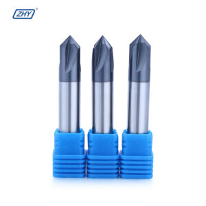
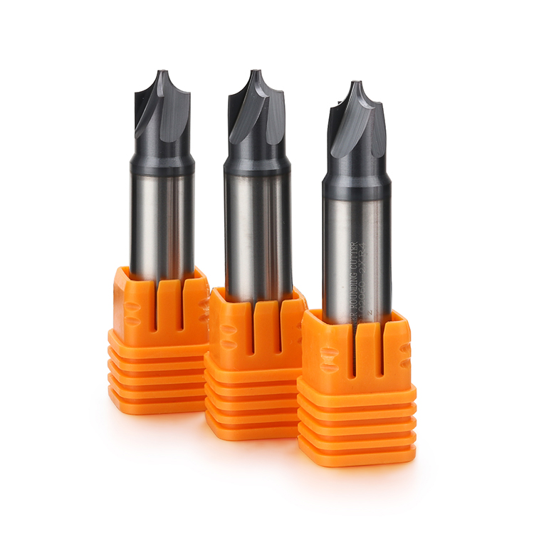
This solid carbide corner rounding end mill is designed
for precision machining of external radii, rounded edges
and formed transitions on housings, frames, brackets,
mold parts, machine components and other precision metal parts.
Also described as an internal-R end mill or concave-radius
end mill in some markets, the tool uses a concave cutting
profile to generate a controlled convex radius on the
workpiece. Standard radius sizes and drawing-based custom
geometries are available for different component profiles,
materials and machining conditions.
Recommended Corner Rounding Applications
Corner rounding end mills are suitable for components
requiring a repeatable external radius, rounded edge,
formed transition or application-specific convex profile.
External Edge Rounding
Produces controlled rounded edges on housings,
frames, brackets, plates and precision metal components.
Convex Radius Milling
Uses a concave cutting profile to generate
repeatable convex radii on external workpiece edges.
Form and Profile Milling
Suitable for formed transitions, special edge
profiles and component-specific radius features.
Precision Edge Finishing
Supports consistent edge geometry before polishing,
coating, assembly or final component inspection.
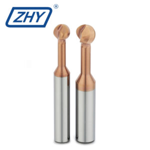
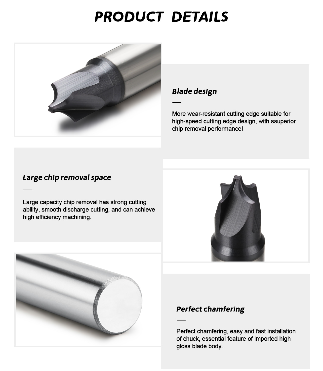
How the Internal-R Cutting Profile Works
The cutting tool contains a precision-ground concave
radius profile. When this profile moves along an external
component edge, it forms the corresponding convex radius
on the workpiece.
Concave Tool Profile
- Concave cutting edge formed to the required radius
- Generates a convex radius on the workpiece edge
- Supports repeatable radius geometry in batch production
- Available in standard and customized radius sizes
- Pilot diameter can be matched to component clearance
- Cutting position should follow the confirmed tool drawing
Component Edge Formation
- Suitable for external edges and projecting features
- Can produce complete or partial rounded profiles
- Useful for housing, frame and bracket transitions
- Reduces the need for multiple contouring passes
- Supports consistent form machining
- The first machined radius should be inspected during setup
Corner Rounding End Mill vs Corner Radius End Mill
These two tool names are sometimes confused, but their These
cutting profiles and machining purposes are different.
Corner Rounding End Mill
- Uses a concave radius cutting profile
- Produces a convex radius on an external edge
- Used for edge rounding and form machining
- Often includes a pilot or tip section
- Outside diameter is larger than the pilot diameter
- This is the tool type shown on this page
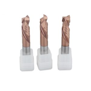
Corner Radius End Mill
- Uses a convex radius at the end of the cutter
- Produces internal fillets and radiused cavity corners
- Commonly used for pocket and shoulder milling
- Strengthens the junction between end and side cutting edges
- Does not produce the same external rounded profile
- Should be selected as a separate cutter type
Corner Rounding End Mill Design and Performance
Radius profile, pilot diameter, outside diameter,
cutting width, flute geometry, carbide grade and coating
are selected together according to the component drawing,
workpiece material and machining conditions.
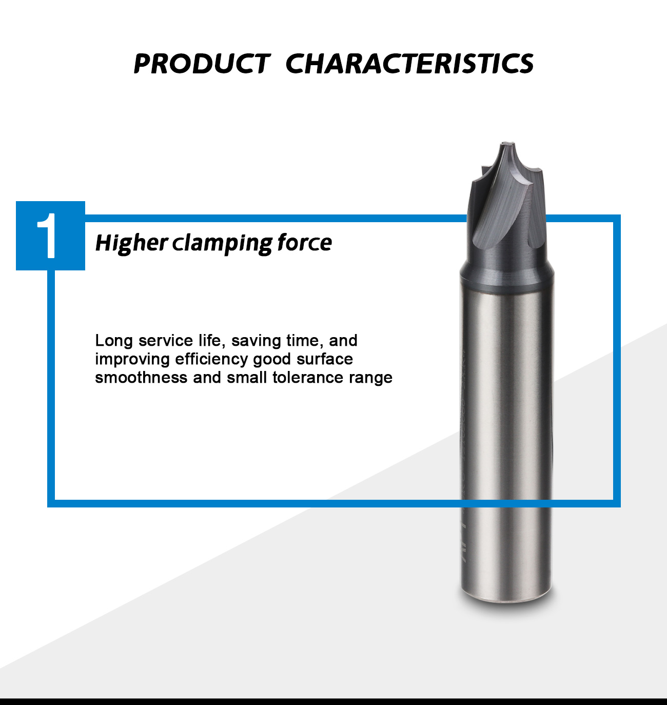
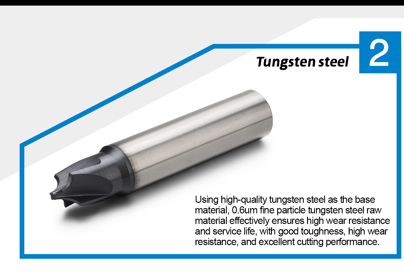
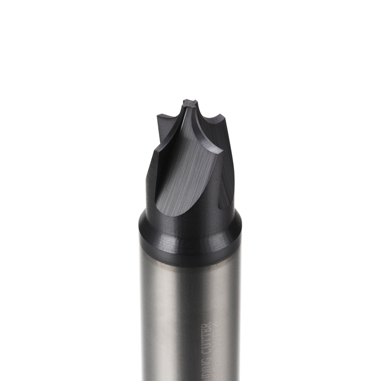
Solid Carbide Construction
Solid carbide provides rigidity, wear resistance
and dimensional stability for precision form
and external-edge machining.
Concave Radius Geometry
The cutting edge follows a controlled concave
profile to generate the required convex radius
on the component.
Standard Radius Range
The current standard range includes radius
dimensions from R0.5 to R6 for different
component-edge requirements.
Four-Flute Standard Design
The current standard configuration uses four
cutting edges for productive and stable
form-milling operations.
Controlled Pilot Diameter
Pilot or tip diameter can be matched to the
available workpiece clearance and required
radius position.
Stable Radius Position
Precision-ground geometry supports a consistent
relationship between the radius, pilot section
and maximum outside diameter.
Reduced Machining Steps
The formed cutting profile can machine the required
radius without reproducing the shape through
numerous contouring passes.
Batch Production Consistency
Stable radius geometry supports repeatable external
edge profiles across multiple components.
Custom Radius Geometry
Non-standard radius dimensions can be developed
according to the component drawing and
required edge profile.
Custom Pilot and Outside Diameter
Pilot diameter and maximum cutting diameter
can be adjusted according to component clearance,
radius size and profile accessibility.
Application-Specific Coating
Carbide grade and coating can be selected according
to the workpiece material, hardness, cutting speed
and coolant method.
Drawing-Based Customization
Radius, pilot diameter, outside diameter,
cutting width, shank diameter and overall length
can be produced according to customer drawings.
Typical Industry Applications
Corner rounding cutters can be used across different
industries wherever an external component edge requires
a controlled and repeatable convex radius.
Available Workpiece Material Applications
The final carbide grade, coating and cutting geometry
should be selected according to the exact component
material, material condition and machining parameters.
Material compatibility must be confirmed before ordering.
Aluminum, stainless steel, mold steel and other materials
may require different carbide grades, coatings and
cutting-edge treatments.
Standard Radius Size List
The current standard product range covers R0.5 to R6.
The reference outside diameters below are based on the
existing standard product list.
| Product Code | Radius R | Reference Outside Diameter |
|---|---|---|
| DZ00037 | R0.5 | 2.7 mm |
| DZ00038 | R0.75 | 3.2 mm |
| DZ00039 | R1 | 3.7 mm |
| DZ00040 | R1.25 | 4.2 mm |
| DZ00041 | R1.5 | 4.7 mm |
| DZ00042 | R1.75 | 5.2 mm |
| DZ00043 | R2 | 5.7 mm |
| DZ00044 | R2.5 | 6.7 mm |
| DZ00045 | R3 | 7.7 mm |
| DZ00046 | R4 | 10.2 mm |
| DZ00047 | R5 | 13.2 mm |
| DZ00048 | R6 | 15.2 mm |
Unit: mm. Pilot diameter, cutting width, shank diameter
and overall length should be confirmed against the current
tool drawing before ordering. Special radius and dimensional
combinations are available on request.
Product Configuration Overview
| Tool Type | Solid Carbide Corner Rounding End Mill |
|---|---|
| Alternative Names | Internal-R End Mill / Concave Radius End Mill / Corner Rounding Cutter |
| Tool Material | Solid Carbide |
| Cutting Profile | Concave Radius Form |
| Standard Flute Configuration | 4 Flutes |
| Standard Radius Range | R0.5–R6 |
| Reference Outside Diameter Range | Approximately 2.7–15.2 mm |
| Main Operations | External Edge Rounding / Convex Radius Milling / Form Milling / Profile Transition Machining |
| Typical Applications | Electronic Components / Automotive Parts / Aerospace Components / Mold Parts / Frames / Brackets / Precision Hardware |
| Coating | Selected According to Workpiece Material, Hardness and Machining Conditions |
| Custom Options | Radius / Pilot Diameter / Outside Diameter / Cutting Width / Shank Diameter / Overall Length / Coating |
| OEM Options | Laser Marking / Customer Model Number / Custom Label / Private-Label Packaging |
Recommended Machining Method
Accurate radius machining depends on the tool position,
programmed offset, axial depth, component-edge condition,
workholding rigidity and spindle runout.
Recommended Setup
- Use rigid workholding and a low-runout holder
- Confirm the actual radius and pilot dimensions
- Set the correct axial cutting position
- Use stable side-milling engagement
- Provide effective chip evacuation
- Inspect the first machined radius before batch production
Conditions Requiring Attention
- Incorrect axial position can distort the radius profile
- Insufficient clearance can cause tool interference
- Excessive engagement can increase cutting load
- High runout can create uneven radius dimensions
- Burrs on the original edge can affect the final result
- Toolpath compensation must match the actual tool geometry
Radius Tool Selection Guidelines
The correct cutter should be selected from the required
workpiece radius, available edge clearance, component
geometry and machining direction.
Select the Radius Profile
- Confirm the required finished radius
- Check whether a full or partial radius is required
- Review the radius tolerance
- Confirm the workpiece material and hardness
- Allow for coating and finishing-process requirements
- Use the component drawing for non-standard profiles
Check Tool Clearance
- Confirm the available pilot clearance
- Check the maximum outside diameter
- Confirm nearby shoulders and walls
- Review the required cutting width
- Check shank and holder interference
- Simulate the toolpath for restricted component areas
Custom Corner Rounding End Mill Options
Non-standard tools can be developed according to the
component edge, required radius, available clearance,
workpiece material and production requirement.
Information Required for Tool Selection
Complete component information helps confirm the radius,
pilot clearance, outside diameter, cutting width,
tool length and suitable cutting configuration.
Component Information
- 2D drawing or 3D component model
- Required radius dimension
- Workpiece material and hardness
- Edge position and available clearance
- Required radius tolerance
- Surface and appearance requirements
Machining Information
- Machine type and spindle condition
- Required pilot and outside diameter
- Toolholder type and measured runout
- Required shank diameter and overall length
- Coolant, air blast or dry-machining condition
- Expected production quantity
Custom Corner Rounding Tool Development Process
Custom geometry is developed according to the component
radius, tool access, workpiece material and production
requirements.
Corner Rounding End Mill Manufacturer
ZHY supplies standard and drawing-based corner rounding
end mills to electronics manufacturers, automotive suppliers,
aerospace machining companies, mold manufacturers,
precision machining companies, distributors and
private-label cutting-tool brands.
Application and Production Support
- Standard radius range from R0.5 to R6
- Custom radius and pilot dimensions
- Application review based on component material
- Prototype tools for radius-profile verification
- Standard and custom batch production
- Mixed-size and mixed-model quotations
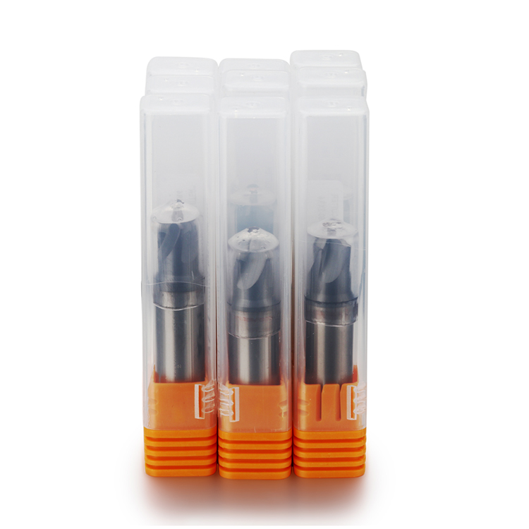
OEM and Private Label
- Customer logo laser marking
- Customer model and product numbers
- Custom labels and barcode stickers
- Plastic box and outer-carton options
- Private-label packaging support
- Packaging verification before shipment
Production and Quality Inspection
Radius profile, pilot diameter, outside diameter,
cutting width, flute geometry and cutting-edge appearance
are inspected to support repeatable form machining.
Explore More Custom End Mills
View additional custom-profile and special-purpose
carbide milling cutters for precision component machining.
Request a Corner Rounding End Mill Recommendation
Send us the component drawing, required radius,
workpiece material, pilot clearance, outside diameter,
cutting width, shank diameter, overall length,
dimensional tolerance, surface requirement and order quantity.
Our team will review the application and recommend a suitable
standard or customized solid carbide corner rounding end mill.