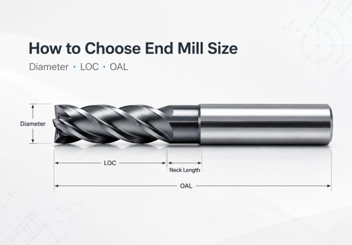
How to Choose End Mill Diameter, Cutting Length and Overall Length
August 28, 2026Choosing an end mill by diameter alone can lead to problems even when the tool appears to fit the component. Two carbide end mills may have the same cutting diameter but very different cutting lengths, neck lengths, reaches and overall lengths, which can produce very different machining behavior.
A cutter that is longer than necessary may lose rigidity and become more sensitive to deflection, chatter and breakage. On the other hand, a tool that is too short may not reach a deep pocket, tall wall or recessed feature without interference between the toolholder, shank and workpiece.
For this reason, end mill size selection should consider the complete tool geometry rather than only the nominal diameter. This guide explains how to choose cutting diameter, cutting length, neck length, reach, shank diameter and overall length according to the actual machining feature.
What Do End Mill Dimensions Mean?
Before selecting a carbide end mill, it is important to distinguish several dimensions that are often confused with one another.
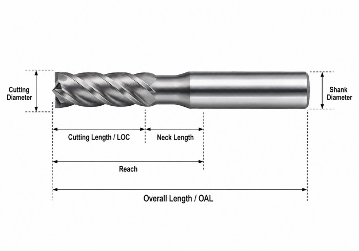
| Dimension | Meaning | Why It Matters |
|---|---|---|
| Cutting Diameter | Diameter of the cutting section | Determines feature accessibility, slot width, rigidity and cutting capacity |
| Shank Diameter | Diameter of the section clamped by the holder | Must match the toolholder or collet specification |
| Cutting Length / LOC | Axial length of the cutting edges | Determines how much axial feature depth the cutting edge can cover |
| Neck Length | Relieved section between the cutting edge and full-diameter shank | Provides clearance for deeper walls, pockets and narrow features |
| Reach | Usable distance allowing the cutter to access a feature | Important for deep cavities and recessed machining areas |
| Overall Length / OAL | Total physical length of the tool | Affects machine clearance and potential setup reach |
| Tool Overhang | Actual length extending from the toolholder during machining | Directly affects rigidity, deflection and vibration |
These dimensions are related, but they are not interchangeable. In particular, cutting length, reach, overall length and actual tool overhang should not be treated as the same specification.
How to Choose End Mill Diameter
The cutting diameter should first be selected according to the geometry of the component. The cutter must physically enter the required slot, pocket, internal corner or machining area while leaving sufficient clearance for the programmed toolpath.
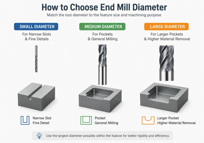
In general, a larger diameter provides a stronger cross-section and greater rigidity, but the largest possible cutter is not automatically the correct choice. The component geometry determines the maximum usable diameter.
Smaller Diameter End Mills
Small-diameter cutters are commonly required for narrow slots, small pockets, fine mold details, small internal radii, micro features and detailed contour machining.
However, as the cutter becomes smaller, rigidity decreases and sensitivity to runout, feed setting, toolholding and cutting load increases. Small-diameter carbide end mills should therefore be used with controlled overhang and stable machine conditions.
Larger Diameter End Mills
Larger cutters can provide greater rigidity and material-removal capability when sufficient space is available. They are often suitable for larger pockets, side milling, roughing and machining broad surfaces.
The machine spindle, holder, available power, workpiece rigidity and cutting engagement must still be considered. A larger end mill cannot compensate for an unstable machining setup.
Diameter is therefore only the first selection step. Workpiece material and tool geometry must also match the application. ZHY’s guide to choosing carbide end mills by workpiece material explains how different materials change cutting-edge, coating and geometry requirements.
How to Choose Cutting Length
Cutting length, sometimes described as length of cut or LOC, is the axial length of the cutter that contains cutting edges.
The cutting length needs to cover the required machining feature, but selecting considerably more flute length than necessary is usually not beneficial.
A longer cutting section extends the flexible cutting portion of the tool and can make the cutter more sensitive to deflection and vibration, especially when the tool diameter is small or machining loads are high.
Use the Shortest Practical Cutting Length
A practical rule is to select enough cutting length to machine the required axial feature while avoiding unnecessary additional flute length.
For example, if a component requires relatively shallow side milling, there is usually no advantage in selecting a very long flute simply because the overall tool needs additional reach.
This distinction becomes especially important in mold cavities, deep pockets and tall-wall machining.
Cutting length should also not be confused with axial depth of cut per pass. A cutter may have a 20 mm cutting length, but this does not mean that every machining condition allows a 20 mm axial depth in one pass. Suitable engagement depends on the workpiece material, cutter geometry, diameter, toolpath, machine rigidity and cutting parameters.
Cutting Length vs Neck Length vs Reach
Deep machining does not always require a long cutting edge. In many applications, the tool only needs a relatively short cutting section combined with additional neck clearance.
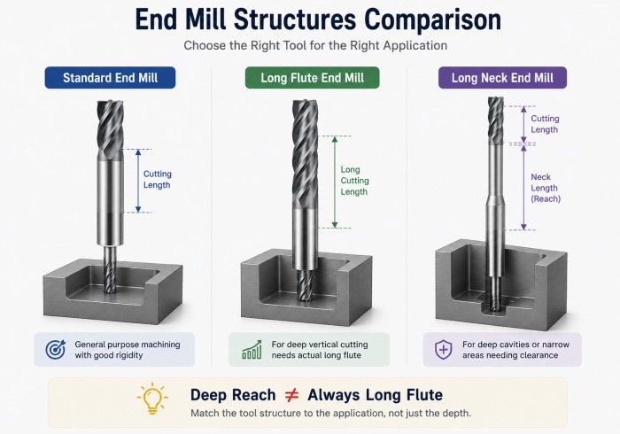
Standard End Mill
A standard-length cutter is usually preferred when the component can be reached without additional neck or overall length. The shorter structure generally provides better rigidity and simpler toolholding conditions.
Long-Flute End Mill
A long-flute end mill has an extended cutting-edge section. It is useful when the tool must actually cut along a relatively tall wall or deep axial feature.
However, long cutting edges should not be selected only because the pocket is deep. If only the bottom or a limited section of a deep feature requires cutting, excessive flute length can reduce tool rigidity unnecessarily.
Long-Neck End Mill
A long-neck end mill uses a relieved neck behind a shorter cutting section. This structure allows the tool to reach deeper into cavities or narrow features while preventing the larger shank from contacting the workpiece wall.
Long-neck end mills are particularly useful for deep mold cavities, tall side walls, narrow recessed features, deep grooves, 3D mold profiles and machining areas where additional holder or shank clearance is required.
Therefore, when machining deep features, it is important to determine whether the application requires a long cutting edge or simply additional reach and neck clearance. These are two different requirements.
How to Choose Overall Length
Overall length is the complete physical length of the cutter from the tool tip to the end of the shank.
A longer overall length can help when a part contains deep or difficult-to-access features, but increasing OAL does not automatically increase usable cutting depth.
The actual usable reach depends on the combination of cutting length, neck geometry, shank diameter, toolholder dimensions, part-wall clearance and required tool projection.
For example, a cutter may have a long overall length but still be unable to enter a narrow deep cavity if the full-diameter shank contacts the wall.
This is why component geometry should be reviewed together with the cutter drawing rather than selecting OAL as an isolated dimension.
Why Tool Overhang Matters
Tool overhang is not the same as overall tool length. It describes the actual amount of the cutter projecting from the toolholder during machining.
Two identical carbide end mills can behave differently if one is clamped with a short projection and the other extends much farther from the holder.
As unsupported tool length increases, the cutter becomes more susceptible to tool deflection, chatter, uneven cutting load, poor dimensional accuracy, surface vibration marks, cutting-edge chipping and premature tool breakage.
Whenever component clearance allows, the cutter should therefore be clamped with the shortest practical projection.
If machining instability is already occurring, excessive tool projection should be one of the first setup conditions checked. The ZHY guide to end mill chatter and vibration explains how overhang, toolholding, workholding and cutting engagement interact during milling.
Standard Length or Long-Reach End Mill?
The correct choice depends on the component geometry rather than on the assumption that a longer cutter is more versatile.
| Machining Condition | Practical Tool Choice |
|---|---|
| Open feature with easy access | Standard-length end mill |
| Shallow slot or pocket | Short practical cutting length |
| Tall wall requiring cutting over most of its height | Longer cutting length may be required |
| Deep cavity with limited cutting near the bottom | Long-neck or reduced-neck end mill |
| Narrow deep feature | Check neck diameter and shank clearance |
| Special reach or interference problem | Custom end mill geometry may be required |
A standard-length tool should normally be preferred when extra reach is unnecessary. Long-reach configurations are application-specific tools rather than an automatic upgrade from standard cutters.
How Workpiece Material Changes Size Selection
The same cutter dimensions do not behave identically in every material.
Aluminum, for example, generally produces a larger chip volume and benefits from sufficient flute space and sharp cutting geometry. Stainless steel introduces higher heat, work-hardening risk and more demanding chip-control conditions. Hardened steel places greater emphasis on cutter rigidity and cutting-edge strength.
As machining difficulty increases, unnecessary cutter length and overhang become increasingly undesirable because the tool must resist higher cutting loads while maintaining dimensional stability.
Flute count also affects the relationship between chip space and core strength. The comparison of 2-flute, 3-flute and 4-flute end mills explains why the number of cutting edges should be selected together with diameter, material and machining operation.
Metric vs Inch End Mill Sizes
International buyers may work with either metric or inch tool dimensions. These systems should not be treated as interchangeable simply because two sizes appear close.
For example, a 1/4-inch cutter has a nominal diameter of 6.35 mm, which is different from a 6 mm end mill. This difference can matter when machining slots, fitting toolholders or maintaining dimensional requirements.
When selecting tooling, follow the units specified on the component drawing, confirm the actual cutting diameter, confirm the shank diameter separately, and check the permitted clamping range of the toolholder or collet.
A nearby metric or inch size should not be substituted without checking the component tolerance and machining requirements.
For OEM and distributor orders, the complete dimension specification should be confirmed rather than referring only to the nominal cutter diameter.
When Do You Need a Custom End Mill Size?
Standard cutter dimensions cover many machining applications, but some components require special combinations of diameter, cutting length, neck diameter, reach, shank size or overall length.
Custom dimensions may be useful when a standard cutter cannot reach the machining feature, a long standard flute creates unnecessary flexibility, the shank interferes with a deep cavity wall, a special cutting diameter is required, or a reduced neck is needed for clearance.
Custom tooling can also be useful when several dimensions need to be combined into one cutter or when repeat production justifies an application-specific tool design.
In these cases, a drawing-based solution can balance cutting access with tool rigidity instead of simply increasing overall length. ZHY’s custom end mill solutions include special diameters, cutting lengths, neck geometries, profiles and application-specific configurations.
Information to Provide When Ordering End Mills
Providing complete dimensions helps the tool manufacturer determine whether a standard cutter is suitable or whether a modified or custom design should be considered.
For a carbide end mill inquiry, it is helpful to provide:
- Workpiece material
- Material hardness
- Tool type: square, ball nose or corner radius
- Cutting diameter
- Shank diameter
- Cutting length
- Required neck length or reach
- Overall length
- Flute number
- Corner radius or ball radius if applicable
- Machining operation
- Required quantity
- Component or tool drawing for special applications
This information is particularly important for long-reach tools because small changes in neck diameter, reach or cutting length can affect both clearance and tool rigidity.
End Mill Size Selection Checklist
Before selecting an end mill size, check the following conditions in sequence:
- Confirm the workpiece material. Tool geometry and coating should match the material first.
- Identify the machining feature. Determine the slot width, pocket size, wall height, cavity depth and internal radius.
- Select the largest practical cutting diameter while maintaining the required feature clearance and toolpath.
- Choose only the cutting length actually required. Avoid unnecessary long flute sections.
- Check neck clearance and determine whether a long-neck or reduced-neck cutter is required.
- Confirm usable reach and make sure the cutter and holder can access the feature without interference.
- Select overall length according to the actual access requirement.
- Minimize actual tool overhang. Clamp the cutter as short as practical while maintaining safe clearance.
- Check flute count and tool geometry so that chip space, core strength and cutting-edge number match the application.
- Consider a custom tool when standard dimensions force an unnecessary compromise.
Conclusion
Choosing the correct end mill size requires more than matching the cutter diameter to the part drawing. Cutting diameter determines feature accessibility and influences rigidity, while cutting length determines how much of the tool can actively cut along the axial direction. Neck length and reach provide clearance for deep features, and overall length determines the physical tool length available for the setup.
At the same time, unnecessary length can reduce machining stability. The most practical approach is therefore to use the largest suitable diameter, the shortest cutting length that covers the required feature and the minimum tool projection that safely reaches the machining area.
For standard carbide cutters, ZHY provides a range of solid carbide end mills for different workpiece materials and machining operations. For special diameters, long-neck structures, extended reach or drawing-based dimensions, send ZHY your tool requirements or component drawing for evaluation.