Description
Product Overview
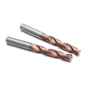
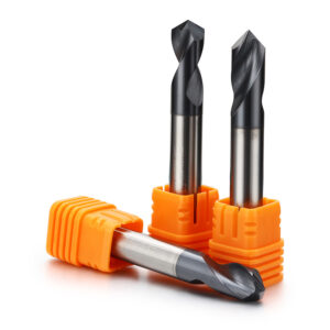
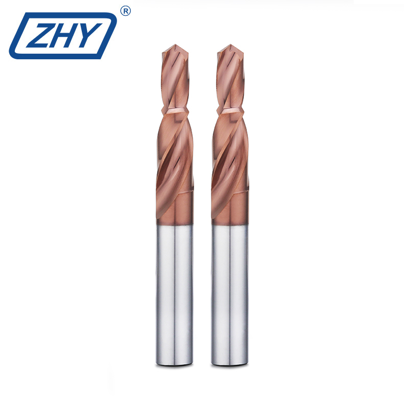
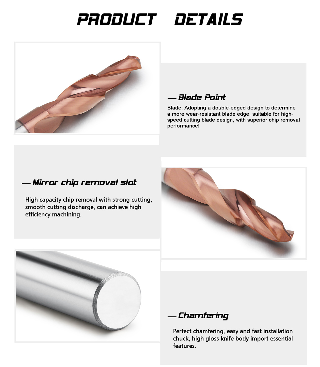
This custom solid carbide step drill is designed to machine multiple hole diameters, shoulders, chamfers or counterbore-related features with one integrated cutting tool. Combining several cutting stages into one drill can reduce tool changes and help maintain a more consistent relationship between connected hole features.
Step diameters, step lengths, point geometry, transition angles, overall length, shank dimensions, coating and coolant configuration can be developed according to the customer drawing, workpiece material and machining conditions. The product is suitable for OEM projects, recurring production parts and applications where standard drills cannot produce the required hole form.
Combined Machining Functions
The step structure can combine several related hole-machining features in one tool, depending on the confirmed drawing and application.
Multiple Hole Diameters
Two or more diameters can be integrated into one drill for stepped-hole machining without changing separate tools.
Shoulder Formation
Step transitions can form controlled shoulders between connected hole diameters according to the component drawing.
Chamfer Integration
A suitable chamfering section can be integrated to machine the hole entrance or a transition feature during the same operation.
Formed Hole Features
Custom profiles can be developed for selected counterbore, seating or application-specific hole forms.
Application Benefits of a Custom Step Drill
Integrating related hole features into one tool can simplify machining processes when the step geometry is correctly matched to the workpiece and machine.
Fewer Tool Changes
Several drilling and forming stages can be completed with one tool, reducing the number of separate tools used in the process.
Consistent Step Position
Integrated cutting sections help maintain the axial relationship between hole diameters, shoulders and chamfers.
Reduced Setup Complexity
Combining multiple features can simplify tool management and reduce repeated positioning between separate operations.
Suitable for Repeat Production
Drawing-based step drills are suitable for recurring components with stable dimensions and repeated hole features.
Material-Specific Design
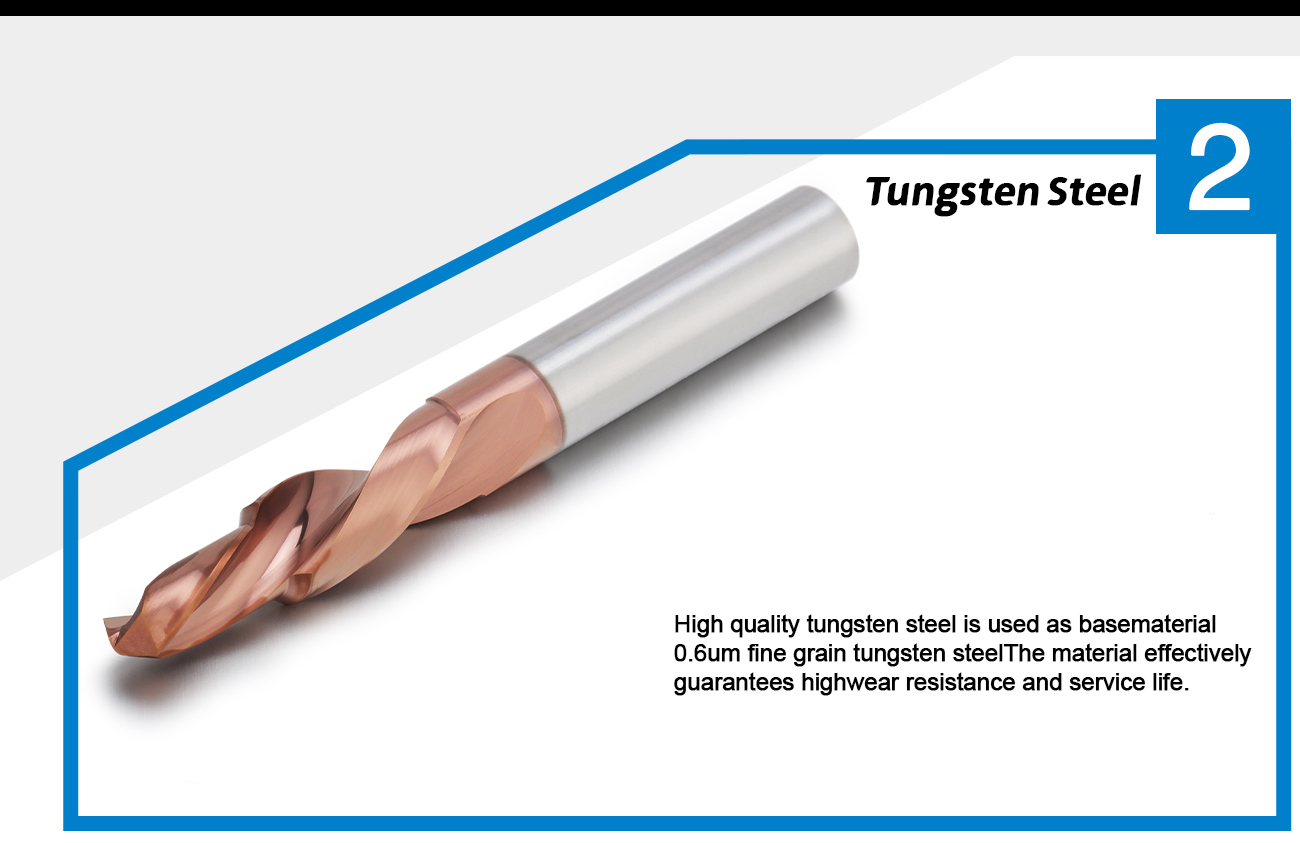
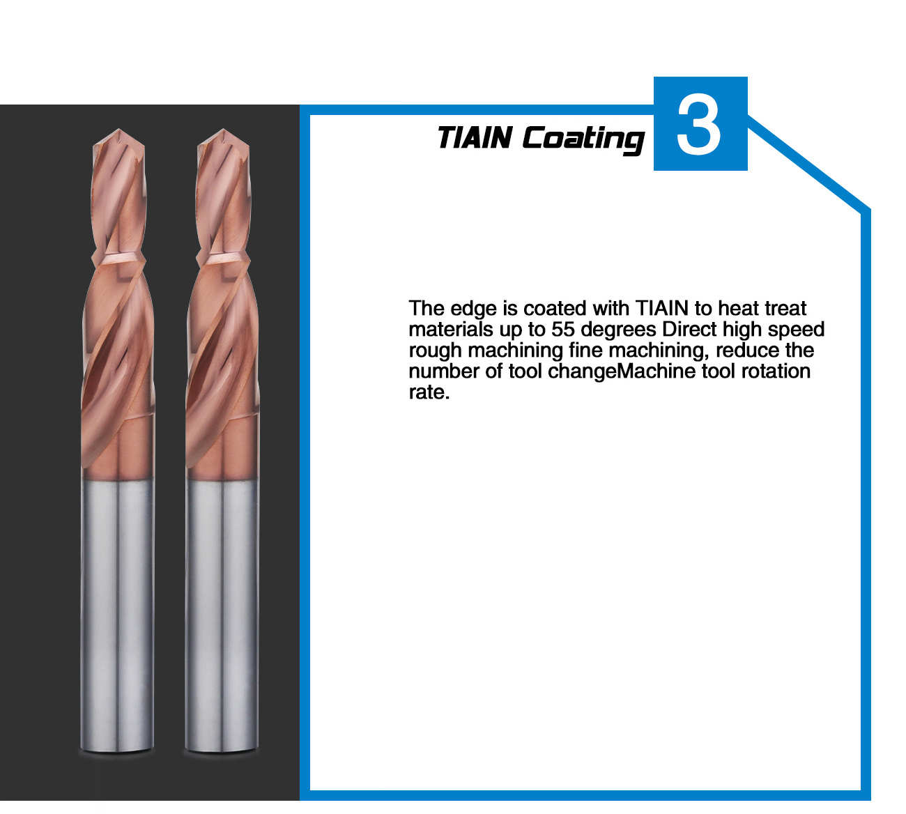
Carbide grade, coating, point geometry and edge preparation can be selected according to the workpiece material.
Custom Coolant Options
External or internal coolant configurations can be reviewed according to the drill diameter, hole depth and machine coolant system.
A Component Drawing Is Required
Step diameters, step lengths, transition angles, hole depth, tolerance, workpiece material, machine condition and coolant method should be confirmed before the final drill structure is designed.
Custom Step Geometry
The following dimensions can be developed according to the finished-hole drawing and machining process.
| First-Step Diameter | Custom According to Drawing |
|---|---|
| Second-Step Diameter | Custom According to Drawing |
| Additional Steps | Available After Geometry Review |
| Step Lengths | Individually Customized |
| Transition Angle | Square Shoulder / Chamfer / Custom Profile |
| Point Geometry | Selected According to Material and Entry Condition |
| Shank Diameter | Standard Shank / Custom Shank |
| Overall Length | Custom According to Machine Clearance |
Please provide a dimensioned drawing showing every diameter, step length, angle, tolerance, surface requirement and overall tool-clearance condition.
Available Tool Configurations
Each step drill is reviewed according to the required hole form, machining material, production quantity and available machine conditions.
| Tool Type | Custom Solid Carbide Step Drill |
|---|---|
| Tool Material | Solid Carbide |
| Number of Steps | According to Drawing and Tool Strength Review |
| Flute Structure | Application-Specific Spiral Flute |
| Coating | Selected According to Workpiece Material |
| Coolant Method | External Coolant / Internal Coolant After Review |
| Dimensional Tolerance | According to Confirmed Drawing |
| Laser Marking | ZHY Logo / Customer Logo / Customer Model Number |
| Packaging | Standard Packaging / Private-Label Packaging |
Workpiece Material Options
The carbide grade, coating, cutting geometry and coolant configuration should be selected according to the actual workpiece material.
Information Required for Tool Design
Workpiece and Hole Information
- Workpiece material and material grade
- Finished-hole drawing
- Each step diameter and tolerance
- Each step length and depth
- Shoulder, chamfer and transition angles
- Through-hole or blind-hole condition
- Required surface or hole-quality level
Machine and Order Information
- Machine type and spindle information
- Toolholder and available shank size
- External or internal coolant system
- Available coolant pressure
- Required production quantity
- Trial quantity or batch quantity
- Marking and packaging requirements
From Drawing to Custom Step Drill
The tool structure is developed after reviewing the component drawing and actual machining conditions.
Custom Production and OEM Support
ZHY supplies drawing-based solid carbide step drills for CNC machining companies, distributors, industrial manufacturers and private-label cutting-tool brands.
Custom Tool Support
- Drawing-based step geometry
- Multiple diameter combinations
- Custom step lengths and angles
- Material-specific coating selection
- Trial tools for application evaluation
- Repeat-order specification management
OEM and Private Label
- Customer logo laser marking
- Customer model and product numbers
- Custom labels and barcode stickers
- Individual plastic-box packaging
- Private-label packaging support
- Packaging verification before shipment
Production and Inspection
Step diameters, step lengths, transition angles, point geometry, cutting edges, overall length, marking and packaging are inspected according to the confirmed specification.
Request a Custom Carbide Step Drill Quotation
Send us the finished-hole drawing, workpiece material, step diameters, step lengths, tolerances, coolant condition, required quantity and packaging requirements. Our team will review the application and prepare a suitable custom step-drill proposal.