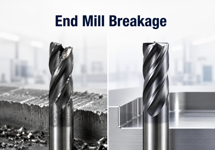
Why Do Carbide End Mills Break? Common Causes and Solutions
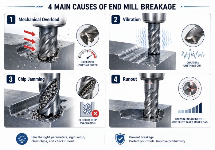
August 14, 2026Carbide end mill breakage is often the final result of a machining problem that has already developed through excessive cutting load, vibration, chip congestion, runout or cutting-edge wear. However, sudden fracture can also occur when the tool experiences an unexpected overload or impact. In many cases, the final fracture is only the last stage of a problem that has already developed through excessive cutting load, vibration, chip congestion, runout or cutting-edge wear.
Because cemented carbide combines high hardness and wear resistance with lower tolerance for excessive bending and impact than tougher tool materials, machining stability is especially important. A tool may perform normally under one set of conditions and fail quickly when tool overhang, radial engagement, feed, workholding or chip evacuation changes.
The best way to reduce unexpected breakage is therefore to identify the failure mechanism before simply replacing the broken cutter with another identical tool.
What Does End Mill Breakage Look Like?
End mill failure does not always begin with the entire cutter snapping in half. The first signs may appear on only one cutting edge.
Common warning signs include:
- Small chips missing from the cutting edge
- Cracks or local edge fractures
- Uneven flute wear
- Sudden deterioration in surface finish
- Increasing cutting noise or vibration
- Chips becoming irregular
- Material building up around the cutting edge
- One flute wearing much faster than the others
Minor edge chipping can eventually develop into catastrophic fracture when the remaining cutting edges are forced to carry a larger share of the load.
Therefore, inspection should focus not only on whether the cutter is completely broken but also on how the damage started.
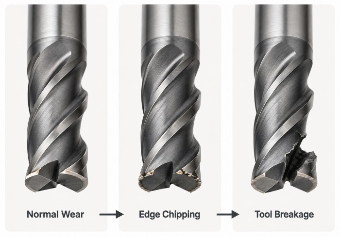
Edge chipping and complete tool fracture are different stages of tool failure. If early cutting-edge damage continues to develop, the remaining flutes may carry higher loads and the risk of catastrophic breakage increases.
Why Do Carbide End Mills Break?
Several problems can produce the same final result. For this reason, a broken cutter should be diagnosed by looking at the complete machining system rather than the tool alone.
1. Excessive Mechanical Load
An end mill can break when the cutting edge receives more load than its geometry and carbide substrate can withstand.
Possible causes include:
- Feed per tooth is too high
- Axial depth is excessive
- Radial engagement is too large
- The tool suddenly enters a heavy corner
- Workpiece hardness is higher than expected
- The tool geometry is too weak for the operation
Heavy chip thickness can overload the cutting edge. However, simply reducing every parameter is not always the best solution because excessively light cutting can also increase rubbing and heat.
The goal is to bring chip thickness and engagement back into a stable range for the specific cutter.
Excessive chip thickness can overload the cutting edge and increase the risk of chipping or complete tool fracture.
2. Excessive Tool Overhang
Long tool projection reduces rigidity and increases deflection.
This commonly occurs when machining:
- Deep mold cavities
- Tall side walls
- Deep pockets
- Features requiring long-neck tools
- Components where the holder must remain far from the workpiece
The longer the unsupported tool length, the easier it becomes for cutting forces to bend the tool.
Therefore, use the shortest practical projection and cutting length that can safely reach the required feature.
3. Chatter and Vibration
Repeated vibration places alternating loads on the carbide cutting edge. Over time, this can produce small chips, cracks and eventually complete fracture.
The source may be:
- Long tool overhang
- Weak workholding
- Poor holder condition
- Unsuitable spindle speed
- Excessive engagement
- Unstable tool geometry
The previous ZHY guide to end mill chatter and vibration explains how rigidity, toolholding and cutting geometry affect machining stability.
Excessive vibration creates repeated impact loads on the carbide cutting edge. Over time, this can accelerate edge chipping, cracking and eventual tool fracture.
4. Chip Jamming and Recutting
A cutter needs enough space to remove chips from the cutting zone.
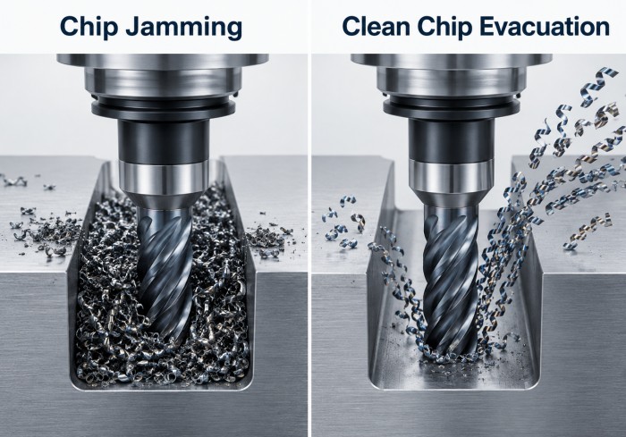
During deep slotting or pocket machining, chips may remain trapped around the tool. The following cutting edge then strikes the same chips again instead of cutting clean workpiece material.
This can increase:
- Cutting load
- Heat
- Edge chipping
- Flute damage
- Tool breakage
Full-slot milling is especially sensitive because the cutter is surrounded by material and the chips have fewer paths to escape.
Flute count also affects chip space. The comparison of 2-flute, 3-flute and 4-flute end mills explains why lower flute counts can provide an advantage when chip evacuation is the dominant problem.
Why Chip Evacuation Can Cause Sudden Tool Breakage
Chip evacuation problems can make a tool appear to break suddenly even though the actual problem developed over several revolutions.
Imagine a deep slot where chips cannot leave quickly enough. Each new flute produces additional chips while previous chips remain inside the slot. Eventually, the available flute space becomes overloaded.
The tool then begins cutting a mixture of workpiece material and previously generated chips.
As a result:
- Cutting forces become irregular
- Heat increases
- Flutes may become packed with material
- Edge loading becomes unpredictable
- Chipping can spread rapidly
Compressed air, correctly directed coolant, sufficient flute space and a suitable toolpath can help remove chips before they are recut.
For deep slotting, reducing the depth into several passes may also improve evacuation when the original cut creates excessive chip congestion.
How Runout and Toolholding Affect End Mill Breakage
Ideally, each flute should remove a similar amount of material.
Excessive runout changes this balance. One cutting edge may project slightly farther than the others and therefore remove a larger chip.
That flute then carries more load while the remaining flutes contribute less.
Over time, this can cause:
- Uneven edge wear
- Local chipping
- Higher vibration
- Poor surface finish
- Premature breakage of the overloaded flute
When unexplained breakage occurs repeatedly, check:
- Collet condition
- Toolholder cleanliness
- Spindle interface
- Tool shank cleanliness
- Tool clamping
- Runout close to the cutting edge
For repeated unexplained breakage, check runout, toolholder condition and tool projection before replacing the cutter. Otherwise, a new end mill may fail again if the original setup problem remains.
How Tool Wear Develops Into Breakage
A carbide end mill should ideally be replaced before normal wear develops into severe edge damage.
As the cutting edge wears, cutting resistance usually rises. The geometry becomes less effective, more heat may be generated and the remaining cutting edge must withstand higher mechanical load.
Eventually, small edge chips can develop.
Once one flute is damaged, the remaining edges may no longer share the machining load evenly. This can accelerate failure.
A common progression is:
Normal Wear
↓
Increasing Cutting Load
↓
Edge Chipping
↓
Uneven Flute Load
↓
Catastrophic Breakage
Coating selection can help manage specific wear mechanisms, but coating alone cannot prevent fracture caused by excessive mechanical loading or poor rigidity. The ZHY guide to end mill coatings explains how coating selection should match material, heat, wear and adhesion conditions.
Can the Wrong End Mill Cause Breakage?
Yes. A cutter can fail even when the machine and cutting parameters appear reasonable if the tool geometry does not match the workpiece or operation.
For example, an aluminum-specific tool emphasizes sharp cutting geometry and open flute space. A hardened-steel end mill generally requires greater edge strength and rigidity.
Using one geometry across very different materials can create problems such as:
- Insufficient edge strength
- Poor chip evacuation
- Excessive cutting force
- Built-up edge
- Premature coating wear
- Edge chipping
Therefore, the workpiece material should be confirmed before adjusting the machining parameters extensively.
The guide to choosing carbide end mills by workpiece material explains the main differences between aluminum, carbon steel, mold steel, stainless steel, titanium, hardened steel and graphite.
ZHY’s current material-specific ranges likewise use different geometry and application positioning for carbon steel, stainless steel, titanium and hardened steel rather than one universal cutter design.
Why End Mills Often Break in Corners
Internal corners can suddenly increase cutter engagement.
During side milling, only part of the tool diameter may be engaged. When the cutter enters a tight internal corner, the contact angle can increase sharply.
This produces a sudden increase in cutting force.
Possible results include:
- Tool deflection
- Chatter
- Edge chipping
- Sudden tool fracture
A toolpath should therefore avoid forcing the cutter into an abrupt high-engagement corner whenever possible.
Controlled cornering strategies and suitable radial engagement can help maintain a more consistent cutting load.
Maintaining a more consistent engagement angle can help reduce abrupt changes in cutting force when machining internal corners.
How Cutting Parameters Contribute to End Mill Breakage
Cutting parameters should be treated as a system.
Feed Too High
Excessive feed per tooth increases chip thickness and mechanical load on each cutting edge.
When the cutting edge cannot withstand the load, chipping or fracture may occur.
Feed Too Low
Very low feed is not automatically safer. The cutting edge may rub instead of forming an efficient chip, which can increase heat and accelerate wear.
Excessive Radial Engagement
Heavy radial engagement increases the amount of tool-workpiece contact and raises cutting force.
This becomes especially important with:
- Long tool overhang
- Difficult materials
- Deep cavities
- Weak fixtures
Excessive Axial Depth
A deep axial cut increases the length of cutting edge engaged in the material.
When combined with high radial engagement, the resulting load can exceed the available rigidity.
Cutting Speed
Cutting speed affects temperature and wear. Therefore, RPM should not be reduced or increased blindly after a tool breaks.
Instead, review:
Material
+
Tool diameter
+
Feed per tooth
+
Radial engagement
+
Axial depth
+
Coolant condition
together.
Chip thickness and mechanical load should be evaluated as a complete system. Feed, speed, radial engagement and axial depth should not be adjusted independently without considering the other cutting conditions.
How Workpiece Material Changes the Breakage Risk
Different materials create different routes to tool failure.
Aluminum
Aluminum can adhere to the flute and cutting edge.
Built-up material may:
- Change effective edge geometry
- Block flute space
- Increase cutting force
- Damage the cutting edge when the adhered material separates
Sharp cutting edges, polished flute surfaces and reliable chip evacuation are important.
Stainless Steel
Stainless steel can generate cutting heat and work-harden when the tool rubs instead of cutting efficiently.
Poor chip evacuation and unstable engagement can further increase cutting-edge stress.
Titanium Alloys
Titanium combines concentrated cutting heat with relatively high cutting loads.
Excessive engagement, long overhang and poor chip removal can accelerate edge damage.
Hardened Steel
Hardened materials place greater emphasis on:
- Edge strength
- Core rigidity
- Runout control
- Short tool overhang
- Controlled radial and axial engagement
The actual heat-treated hardness should be confirmed rather than selecting the cutter by steel grade alone. ZHY similarly recommends selecting hardened-steel cutters according to the actual measured hardness and heat-treatment condition.
How to Prevent Carbide End Mill Breakage
When a cutter breaks, avoid changing several variables at the same time. A step-by-step inspection makes it easier to identify the real cause.
Step 1: Inspect the Broken Tool
Look for:
- Chipping
- Flute blockage
- Built-up material
- Uneven wear
- Heat discoloration
- Wear concentrated on one flute
Step 2: Check Tool Overhang
Reduce projection wherever the component allows it.
Step 3: Check Workholding and Toolholding
Confirm that the part, holder and spindle interface are rigid and clean.
Step 4: Check Runout
Uneven flute loading may indicate holder or spindle runout.
Step 5: Check Chip Evacuation
Look inside slots and cavities for trapped or recut chips.
Step 6: Review Cutting Engagement
Check radial width, axial depth and sudden changes in tool engagement.
Step 7: Review Feed and Speed
Compare the existing parameters with the tool diameter, flute count, workpiece material and machining operation.
Step 8: Confirm Tool Selection
Make sure the carbide grade, flute geometry, coating and tool shape match the workpiece and operation.
A practical breakage diagnosis should therefore begin with rigidity, runout, tool projection, cutting load and chip evacuation before making large changes to the machining program.
End Mill Breakage Troubleshooting Table
| Symptom | Possible Cause | First Check |
|---|---|---|
| Sudden Complete Breakage | Mechanical overload or severe instability | Engagement, feed, overhang and workholding |
| Edge Chipping | Vibration, impact or weak edge geometry | Rigidity, tool geometry and entry conditions |
| One Flute Fails First | Runout or uneven loading | Toolholder, collet and spindle runout |
| Breakage in Deep Slots | Chip jamming or excessive tool reach | Chip evacuation and tool overhang |
| Breakage in Corners | Sudden increase in engagement | Toolpath and radial cutting load |
| Breakage After Progressive Wear | Tool used beyond stable wear condition | Tool-life interval and edge condition |
| Repeated Breakage With New Tools | Setup, holder, parameters or tool mismatch | Complete machining system |
Frequently Asked Questions
Why Does My End Mill Keep Breaking?
Repeated breakage usually indicates that the root cause has not been corrected. Check mechanical load, tool projection, workholding, runout, chip evacuation and whether the cutter is suitable for the material.
Can Too Much Feed Break an End Mill?
Yes. Excessive feed per tooth can create chip thickness and cutting forces that overload the cutting edge.
Can Too Little Feed Damage an End Mill?
Yes. An excessively light feed can cause rubbing rather than efficient chip formation, increasing heat and wear.
Does Long Tool Overhang Increase Breakage Risk?
Yes. Longer unsupported tool length reduces rigidity and increases deflection. Use the shortest practical projection whenever possible.
Can Chip Jamming Break a Carbide End Mill?
Yes. Trapped and recut chips can produce irregular cutting loads, edge chipping and eventually complete fracture.
Can Runout Cause End Mill Breakage?
Yes. Runout can cause one flute to carry significantly more cutting load than the others, creating uneven wear and local edge failure.
Should I Use Fewer Flutes If My End Mill Keeps Breaking in a Slot?
Possibly, especially when chip congestion is the main problem. However, flute count should be evaluated together with tool geometry, material, slot depth, coolant and cutting parameters.
Should I Replace the Tool as Soon as I See Edge Chipping?
Edge chipping indicates that the cutting edge is already damaged. Continuing to use the cutter may increase the risk of further failure, so the cause and remaining tool condition should be evaluated before continued production.
Conclusion
Carbide end mill breakage is usually the final result of an unstable machining condition rather than a random tool failure.
Mechanical overload, excessive overhang, chatter, runout, chip jamming, progressive wear and unsuitable tool geometry can all contribute to fracture. In many cases, several of these problems occur at the same time.
Start by examining the damaged tool and then check rigidity, toolholding, chip evacuation and cutting engagement before making large changes to speed and feed.
For applications involving long reach, difficult materials, special features or repeated tool failure, ZHY can review the workpiece material, hardness, tool diameter, cutting length, machining feature and existing cutting conditions and provide standard or customized carbide end mill solutions.