Description
Product Overview
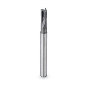
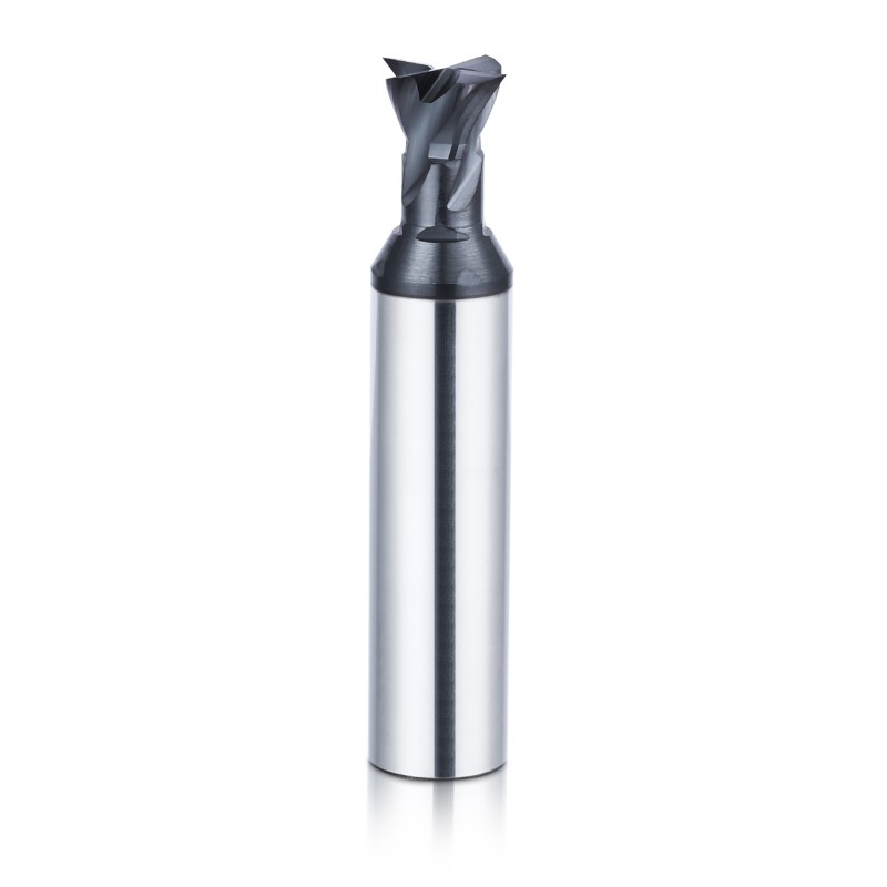
This PCD dovetail end mill is designed for precision
machining of dovetail grooves, undercuts, angled sidewalls,
locking features and recessed profiles in aluminum,
graphite, composites and other abrasive non-ferrous or
non-metallic materials.
The tool combines a rigid carbide body with
application-specific PCD cutting edges. High wear
resistance and stable edge retention help maintain
dovetail angle, groove width and profile consistency
during repetitive production.
Recommended Machining Applications
PCD dovetail end mills are suitable for components requiring
angled groove walls, recessed cutting positions or locking
profiles that cannot be completed with a conventional
square end mill.
Dovetail Groove Milling
Produces dovetail-shaped grooves with controlled
sidewall angles, groove widths and bottom positions.
Undercut Machining
Suitable for recessed profiles and internal features
located behind an opening or shoulder.
Angled Sidewall Milling
Custom tool angles can be developed for inclined
groove walls, guide features and angular transitions.
Locking and Guide Features
Supports precision machining of mechanical locking
grooves, guide tracks and component-specific
dovetail connections.
Why Use a PCD Dovetail End Mill?
Dovetail tools use the cutting edge along an angled profile.
Abrasive workpiece materials can quickly change this profile
when conventional cutting edges wear. PCD helps retain the
cutting angle and groove geometry over longer production runs.
Wear Resistance and Edge Retention
- Suitable for abrasive non-ferrous materials
- Stable cutting profile over longer machining cycles
- Reduced frequency of tool replacement
- Suitable for high-silicon aluminum
- Useful for graphite and fiber-reinforced materials
- Supports repetitive dovetail-groove machining
Profile and Dimensional Consistency
- Helps maintain the specified dovetail angle
- Supports consistent groove width
- Stable cutting edges help reduce profile variation
- Suitable for automated batch production
- Custom geometry can match component drawings
- Final profile can be inspected before shipment
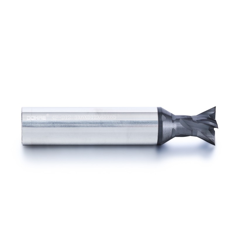
PCD Dovetail Geometry and Cutting Performance
The PCD cutting edges, tool-body rigidity, neck clearance
and dovetail profile are designed together according to
the workpiece material, groove geometry and machining access.
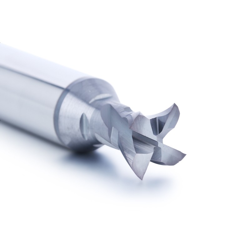
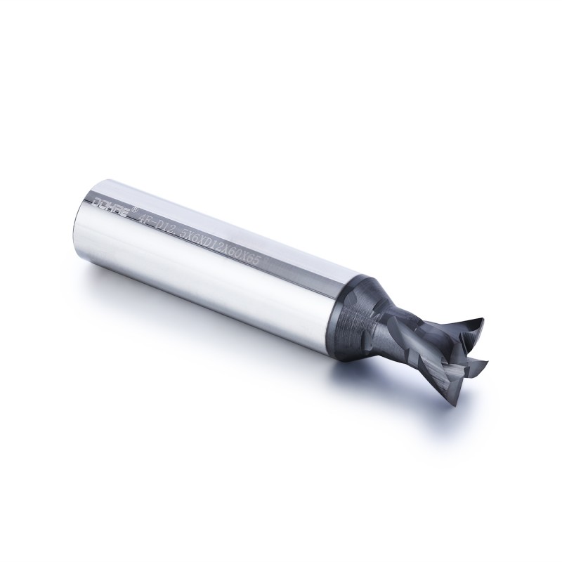
PCD Cutting Edges
Polycrystalline diamond cutting edges provide high
abrasion resistance for aluminum, graphite,
composites and other abrasive materials.
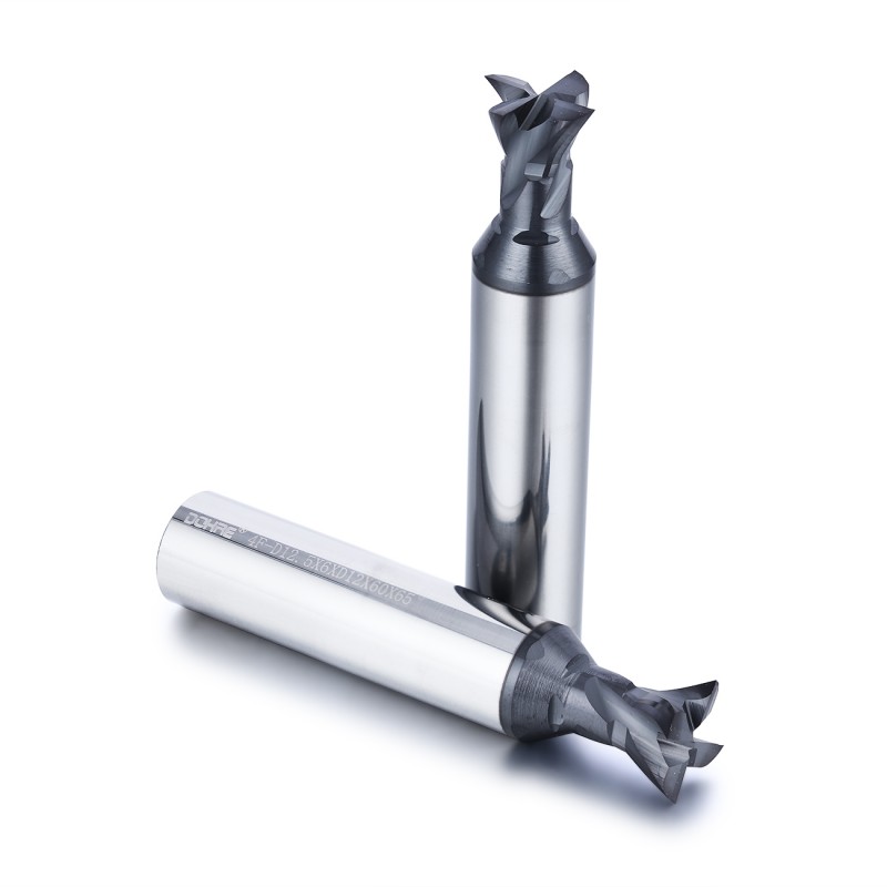
Rigid Carbide Tool Body
The carbide tool body provides structural support
for the PCD cutting sections and helps maintain
stable tool positioning during undercut machining.
Drawing-Based Dovetail Profile
The cutting angle, major diameter, minor diameter
and groove width can be designed according to
the component drawing.
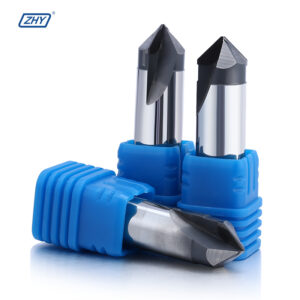
Custom Included Angle
Standard or customized dovetail angles can be
produced according to the required sidewall
geometry and locking profile.
Undercut Cutting Capability
The enlarged cutting head and reduced neck provide
access to recessed groove surfaces and internal
undercut features.
Custom Neck Clearance
Neck diameter and neck length can be adjusted
to avoid interference with groove walls,
shoulders and recessed component areas.
Sharp Cutting Geometry
Precision-ground PCD edges support clean shearing,
low cutting resistance and controlled burr formation
in suitable workpiece materials.
High Wear Resistance
PCD resists abrasive wear caused by silicon particles,
graphite, carbon fibers and glass-fiber reinforcement.
Stable Groove Dimensions
Long-term edge retention helps maintain groove width,
angle and profile dimensions during repeat production.
Custom Cutting-Edge Quantity
Cutting-edge quantity can be selected according
to chip space, groove width, machine feed capability
and productivity requirements.
Custom Cutting Direction
Right-hand or left-hand cutting configurations
can be developed where required by the spindle,
component setup or machining direction.
Regrinding Evaluation
Selected PCD dovetail cutters can be inspected
for regrinding depending on cutting-edge wear,
available PCD material and tool construction.
Recommended Dovetail Machining Method
Dovetail cutters normally require an existing entry slot
or clearance path before the angled profile is machined.
The exact sequence depends on whether the tool has been
specifically designed for center cutting.
Recommended Process
- Machine a pilot slot or clearance groove first
- Confirm sufficient neck and shoulder clearance
- Use a stable side-milling toolpath
- Control radial engagement and cutting load
- Use air blast or suitable chip evacuation
- Inspect groove angle and width during setup
Important Application Notes
- Do not assume that the tool is center cutting
- Avoid excessive axial or radial engagement
- Use rigid workholding and low-runout toolholders
- Avoid collision between the neck and groove wall
- Confirm the included angle used on the drawing
- Verify toolpath clearance before production
Recommended Workpiece Materials
This PCD dovetail end mill is primarily intended for
non-ferrous metals, graphite, composites and abrasive
non-metallic materials.
Available PCD Dovetail Cutter Configurations
Standard and customized PCD dovetail end mills can be
supplied according to the component drawing, groove angle,
groove width, machining depth and tool-access conditions.
| Tool Type | PCD Dovetail End Mill |
|---|---|
| Cutting Material | PCD Cutting Edges |
| Tool Body | Carbide Tool Body |
| Dovetail Angle | Standard Angle / Custom Included Angle |
| Major Cutting Diameter | Drawing-Based Standard or Custom Diameter |
| Minor Diameter | According to Groove and Neck Geometry |
| Cutting Width | Standard / Custom According to Groove Width |
| Neck Diameter | Reduced Neck / Custom Clearance Diameter |
| Neck Length | Standard / Long Reach / Custom |
| Shank Diameter | Standard Shank / Custom Shank |
| Overall Length | Standard / Extended Reach / Custom |
| Cutting-Edge Quantity | According to Tool Design and Application |
| Cutting Direction | Right-Hand / Left-Hand Where Applicable |
| Internal Coolant | Available Where Tool Structure Permits |
| Main Operations |
Dovetail Grooving / Undercutting / Angled Sidewall Milling / Locking Groove Machining |
| OEM Options |
Custom Geometry / Laser Marking / Customer Model Number / Private Label |
Send us the component drawing, included angle,
major diameter, minor diameter, groove width,
groove depth, neck clearance, tool reach,
workpiece material and order quantity for evaluation.
Information Required for Tool Selection
Dovetail tool geometry must match the component profile.
A complete drawing helps prevent incorrect angle,
diameter or neck-clearance selection.
Component Information
- 2D drawing or 3D component model
- Workpiece material and exact grade
- Dovetail included angle
- Groove opening and bottom width
- Groove depth and undercut position
- Dimensional and surface requirements
Machining Information
- Machine type and spindle interface
- Available spindle speed and feed rate
- Toolholder and runout condition
- Pilot-slot size and machining sequence
- Cooling, lubrication or air-blast method
- Expected production quantity
Custom PCD Dovetail Tool Development
The tool profile is developed from the dovetail feature,
machining access and production process rather than
from a general catalogue dimension alone.
PCD Dovetail End Mill Manufacturer and OEM Supplier
ZHY supplies standard and customized PCD dovetail cutters
to component manufacturers, machining companies,
cutting-tool distributors and private-label tool brands.
Application and Production Support
- Drawing-based dovetail profile development
- Standard and customized included angles
- Custom groove width and cutting diameters
- Prototype tools for machining verification
- Mixed-model and batch-order quotations
- Regrinding evaluation where applicable
OEM and Private Label
- Customer logo laser marking
- Customer model and product numbers
- Custom labels and barcode stickers
- Plastic box and outer-carton options
- Private-label packaging support
- Packaging verification before shipment
Production and Profile Inspection
Tool-body dimensions, PCD cutting-edge position and
final dovetail profile are inspected to support repeatable
customized and batch production.
Request a PCD Dovetail End Mill Recommendation
Send us the component drawing, workpiece material,
dovetail included angle, major and minor diameters,
groove width, groove depth, neck-clearance requirement,
machine information, tolerance and order quantity.
Our team will review the application and develop a suitable
standard or customized PCD dovetail end mill.