Description
Product Overview
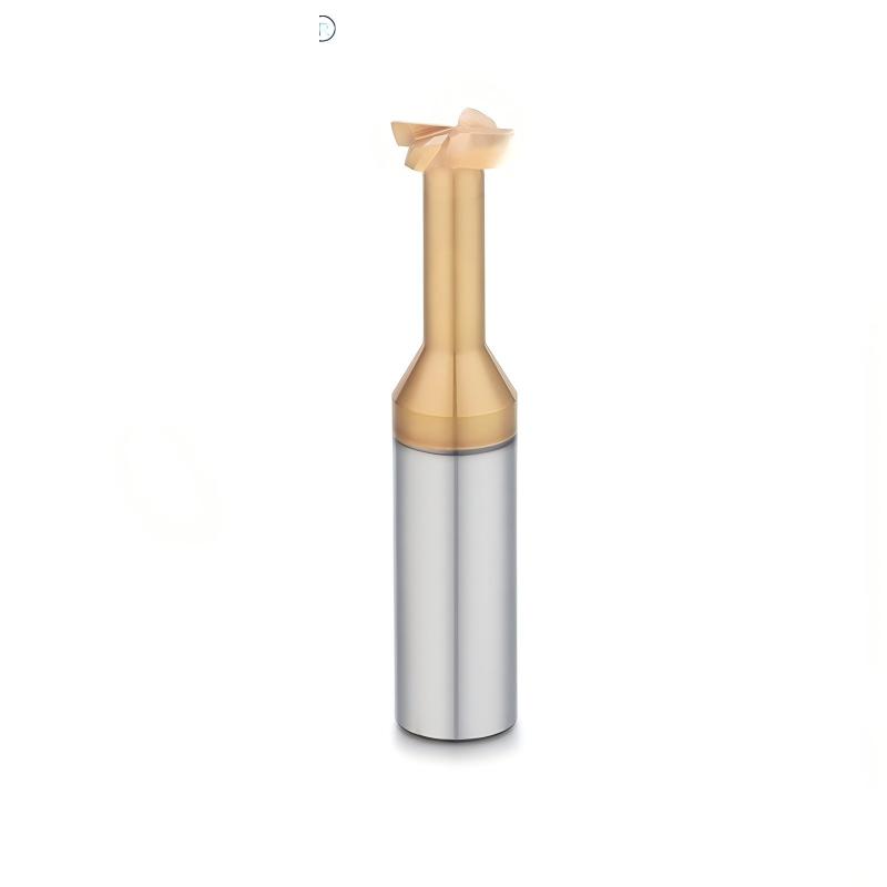
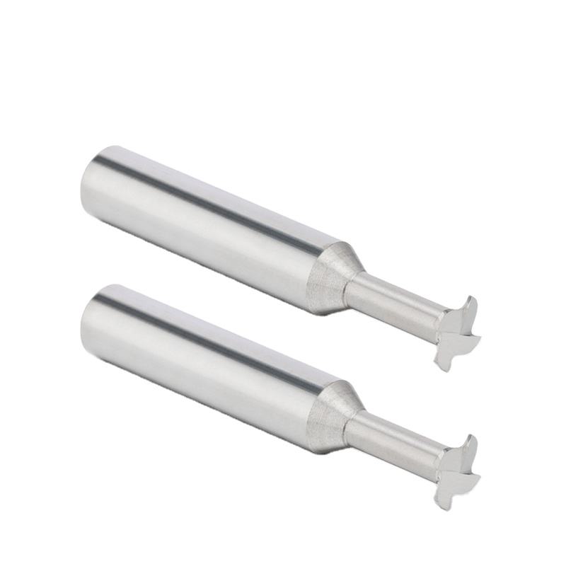
This custom solid carbide T-slot cutter is designed
for machining T-slots, undercut grooves, recessed slots,
clamping features and other component profiles located
below a narrow slot opening.
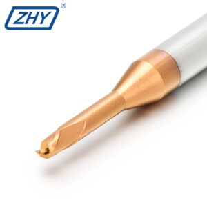
The cutter uses an enlarged cutting head together with
a reduced neck section. After a suitable access slot has
been prepared, the cutting head enters the feature and
moves laterally to machine the wider undercut section
below the slot opening.
Recommended T-Slot Milling Applications
T-slot cutters are suitable for component features where
the internal slot width is larger than the access opening
and cannot be machined directly with a conventional
square end mill.
T-Slot Machining
Machines the wider lower section of a T-shaped
slot after the narrow access slot has been
prepared with another cutter.
Undercut Groove Milling
Suitable for straight undercut grooves and
recessed slot features located below
a smaller opening.
Fixture and Clamping Features
Can be used for fixture slots, clamping grooves
and mechanical features requiring a controlled
lower slot width.
Special Recessed Profiles
Drawing-based cutter geometry can be developed
for special groove widths, corner forms,
reliefs and recessed component profiles.
How a T-Slot Cutter Works
A T-slot is normally produced in two machining stages.
The access slot is created first, and the T-slot cutter
is then moved into the prepared opening to machine
the wider undercut section.
Prepared Access Slot
- A straight slot is normally machined before T-slot milling
- The access width must clear the cutter neck
- The access depth must allow the cutting head to enter safely
- Nearby shoulders and walls should be checked for interference
- The prepared slot must provide sufficient chip space
- The actual access dimensions should match the tool drawing
Lateral Undercut Milling
- The enlarged cutting head machines below the slot opening
- The relieved neck provides clearance from the upper walls
- Lateral movement forms the required lower slot width
- Controlled radial engagement reduces load on the neck
- Chip evacuation is important in enclosed slot features
- Entry and exit paths should be verified before production
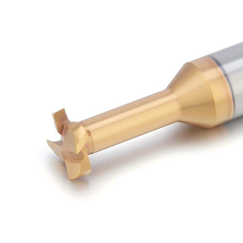
Key T-Slot Cutter Geometry
Cutting-head diameter, slot width, neck diameter,
neck length and corner geometry must work together
to provide the required profile and sufficient tool strength.
Cutting-Head Diameter
The cutting-head diameter determines the maximum
width of the undercut or lower T-slot section.
Slot Cutting Width
The axial thickness of the cutting head determines
the machined T-slot width or recessed groove width.
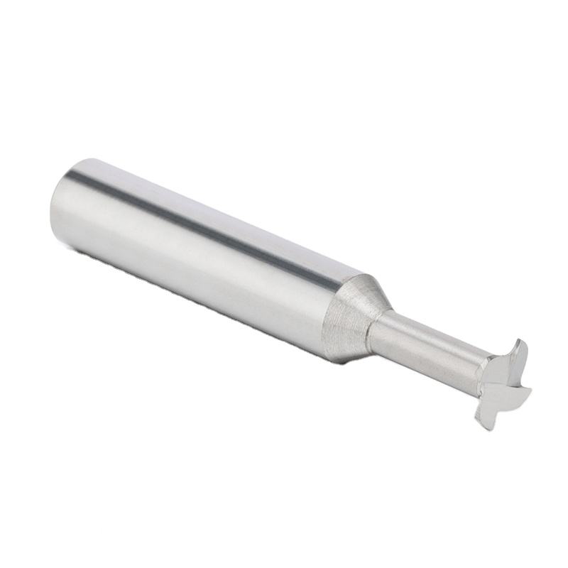
Relieved Neck Diameter
The neck diameter must pass through the access slot
while maintaining sufficient strength for
lateral cutting forces.
Neck Length and Reach
Neck length determines how far the cutter head
can reach below the component surface
or inside a recessed feature.
Solid Carbide T-Slot Cutter Design and Performance
The cutter profile, carbide grade, cutting-edge geometry,
coating and overall dimensions are developed according
to the component drawing and machining conditions.
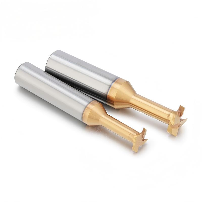
Solid Carbide Construction
Solid carbide provides rigidity, wear resistance
and dimensional stability for precision
undercut and T-slot machining.
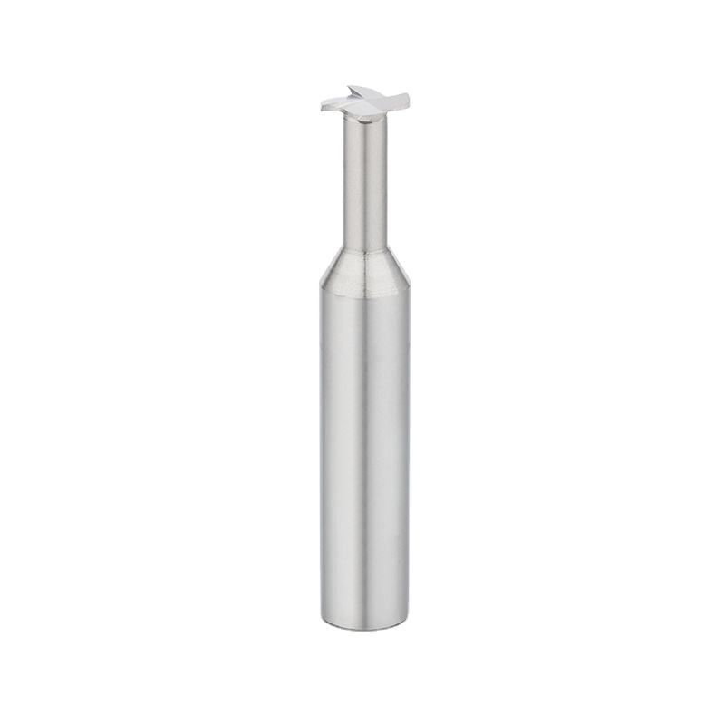
Enlarged Cutting Head
The larger cutting head machines the recessed
lower slot profile while the smaller neck
remains clear of the upper slot walls.
Relieved Neck Structure
The reduced neck provides access to undercut
features and helps prevent interference
with the slot opening.
Controlled Slot Width
Precision-ground head thickness supports
repeatable slot width when cutting position,
runout and tool wear are properly controlled.
Custom Head Diameter
Cutting-head diameter can be developed according
to the required lower slot width and available
component clearance.
Custom Cutting Width
Head thickness can be customized according
to the finished groove width and
tolerance requirement.
Custom Neck Clearance
Neck diameter and length can be designed
according to the access opening,
undercut depth and required reach.
Custom Corner Geometry
Sharp corners, corner radii, chamfers
or profile transitions can be evaluated
according to the component drawing.
Application-Specific Flute Design
Flute quantity, rake geometry and chip space
can be selected according to workpiece material,
slot width and tool strength.
Application-Specific Coating
Carbide grade and coating are selected according
to workpiece material, hardness, cutting speed
and coolant conditions.
Prototype Tool Support
Prototype tools can be produced for slot-width,
profile and machining verification before
batch production.
Drawing-Based Production
Final geometry is manufactured according
to an approved tool drawing based on
the component requirements.
T-Slot Cutter vs Other Undercutting Tools
T-slot cutters, keyseat cutters and lollipop end mills
can all machine recessed features, but their geometry
and primary applications are different.
T-Slot Cutter
Designed for straight T-slots, defined undercut
widths and recessed groove features with
controlled axial dimensions.
Keyseat Cutter
Commonly used for keyways, retaining-ring grooves
and narrow slots requiring a disc-shaped
side-cutting profile.
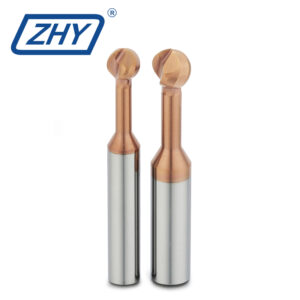
Lollipop End Mill
Uses a spherical cutting head for complex
undercuts, back-side deburring and
multi-axis profile machining.
Custom Form Cutter
Combines several special profiles when the
required recessed feature cannot be produced
by a conventional T-slot geometry.
Typical Component Applications
Custom T-slot cutters can be used wherever a recessed
slot or undercut feature must be machined through
a narrower access opening.
Available Workpiece Material Applications
The carbide grade, flute geometry, edge treatment
and coating should be selected according to the exact
workpiece material, hardness and machining conditions.
Hardened steel, titanium alloys, nickel-based alloys
and other difficult-to-machine materials require
a separately evaluated carbide grade, coating,
cutting geometry and neck-strength design.
Available Custom T-Slot Cutter Configurations
This product is manufactured according to the component
and approved tool drawings. There is no single universal
standard size for every T-slot application.
| Tool Type | Custom Solid Carbide T-Slot Cutter |
|---|---|
| Alternative Names |
T-Slot End Mill / T-Slot Milling Cutter / Undercut Slot Cutter |
| Tool Material | Solid Carbide |
| Cutting Structure | Enlarged Cutting Head with Relieved Neck |
| Cutting-Head Diameter | Drawing-Based Custom Diameter |
| Slot Cutting Width | Custom According to Finished Slot Width |
| Neck Diameter | Custom According to Access-Slot Clearance |
| Neck Length | Standard / Extended / Drawing-Based Custom Reach |
| Corner Geometry |
Sharp Corner / Corner Radius / Chamfer / Custom Profile |
| Flute Configuration |
Selected According to Cutter Diameter, Slot Width and Workpiece Material |
| Shank Diameter | Standard or Customized |
| Overall Length | Standard or Customized |
| Coating |
Selected According to Workpiece Material and Machining Conditions |
| Main Operations |
T-Slot Milling / Undercut Slot Machining / Recessed Groove Milling / Clamping Feature Machining |
| OEM Options |
Laser Marking / Customer Model Number / Custom Label / Private-Label Packaging |
Final cutting-head diameter, slot width, neck diameter,
neck length, corner geometry and tolerances must be
confirmed on the approved tool drawing before production.
T-Slot Cutter Selection Guidelines
Correct tool selection requires the complete slot profile,
not only the nominal cutter diameter.
Confirm the Slot Geometry
- Access-slot width
- Lower T-slot or undercut width
- Finished slot height
- Depth below the component surface
- Corner radius or chamfer requirement
- Dimensional and profile tolerances
Confirm the Tool Configuration
- Cutting-head diameter
- Cutting-head thickness
- Neck diameter and neck length
- Shank diameter and toolholder type
- Overall length and effective overhang
- Available entry and exit path
Recommended Machining Method
T-slot cutter performance depends on a correctly prepared
access slot, controlled radial engagement, low tool runout
and effective chip evacuation.
Recommended Setup
- Machine the access slot before using the T-slot cutter
- Use rigid workholding and a low-runout holder
- Confirm neck and holder clearance
- Use controlled lateral engagement
- Provide effective coolant or chip evacuation
- Inspect the first completed slot before batch production
Conditions Requiring Attention
- Access slot too narrow for the cutter neck
- Excessive radial engagement in one pass
- Insufficient chip evacuation in enclosed slots
- Excessive neck length or tool overhang
- Holder or shank interference with the component
- Plunging without confirmed center-cutting geometry
Entry and Toolpath Considerations
Most T-slot cutters should enter through a prepared
opening rather than plunge directly into solid material.
The entry method must match the actual cutter geometry.
Recommended Tool Entry
- Enter through an open end when possible
- Use a prepared access slot or entry pocket
- Move to the correct axial slot position
- Apply gradual lateral engagement
- Maintain a stable feed around the slot path
- Retract through the confirmed clearance path
Toolpath Verification
- Check the cutting-head path inside the feature
- Confirm the neck remains clear of the upper walls
- Verify shank and holder clearance
- Check internal corners and slot-end geometry
- Confirm the programmed slot width and axial position
- Simulate restricted or enclosed component features
Custom Solid Carbide T-Slot Cutter Options
Non-standard cutters can be developed according to
the finished slot geometry, access opening,
component material and available machine conditions.
Information Required for Tool Development
Complete slot and machining information helps determine
whether the cutter can enter the feature safely and
maintain sufficient neck strength.
Component Information
- 2D drawing or 3D component model
- Access-slot width and depth
- Finished undercut width and height
- Corner radius or chamfer requirement
- Dimensional and profile tolerances
- Workpiece material and hardness
Machining Information
- Machine type and spindle interface
- Toolholder type and measured runout
- Required neck reach and overall length
- Coolant or chip-evacuation method
- Current machining sequence and parameters
- Prototype and batch production quantity
Custom T-Slot Cutter Development Process
Custom geometry is reviewed and confirmed before
prototype manufacturing and repeat production.
Production and Quality Inspection
Cutting-head diameter, slot width, neck dimensions,
corner geometry and cutting-edge condition are inspected
against the approved tool drawing.
Custom Solid Carbide T-Slot Cutter Manufacturer
ZHY supplies drawing-based solid carbide T-slot cutters
to precision machining companies, automotive suppliers,
aerospace manufacturers, mold companies, distributors
and private-label cutting-tool brands.
Engineering and Production Support
- Component and slot-drawing review
- Access and interference analysis
- Custom head, neck and corner geometry
- Material-specific carbide and coating selection
- Prototype tools for slot verification
- Repeat batch production after approval
OEM and Private Label
- Customer logo laser marking
- Customer model and product numbers
- Drawing and revision-number management
- Custom labels and barcode stickers
- Private-label packaging support
- Packaging verification before shipment
Explore More Custom Milling Tools
Browse additional drawing-based and special-purpose
carbide cutters for undercuts, grooves,
profiles and complex component features.
Request a Custom T-Slot Cutter Quote
Send us the component drawing, access-slot width,
finished T-slot width, slot height, undercut depth,
corner geometry, workpiece material, hardness,
toolholder information, machining conditions
and required quantity. Our team will review the application
and develop a suitable custom solid carbide T-slot cutter.