Description
Product Overview
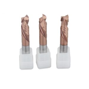
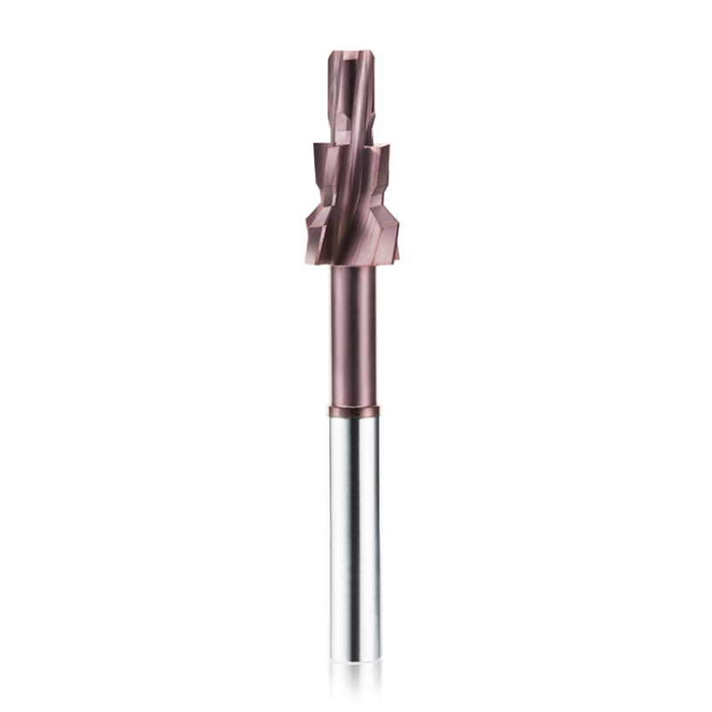
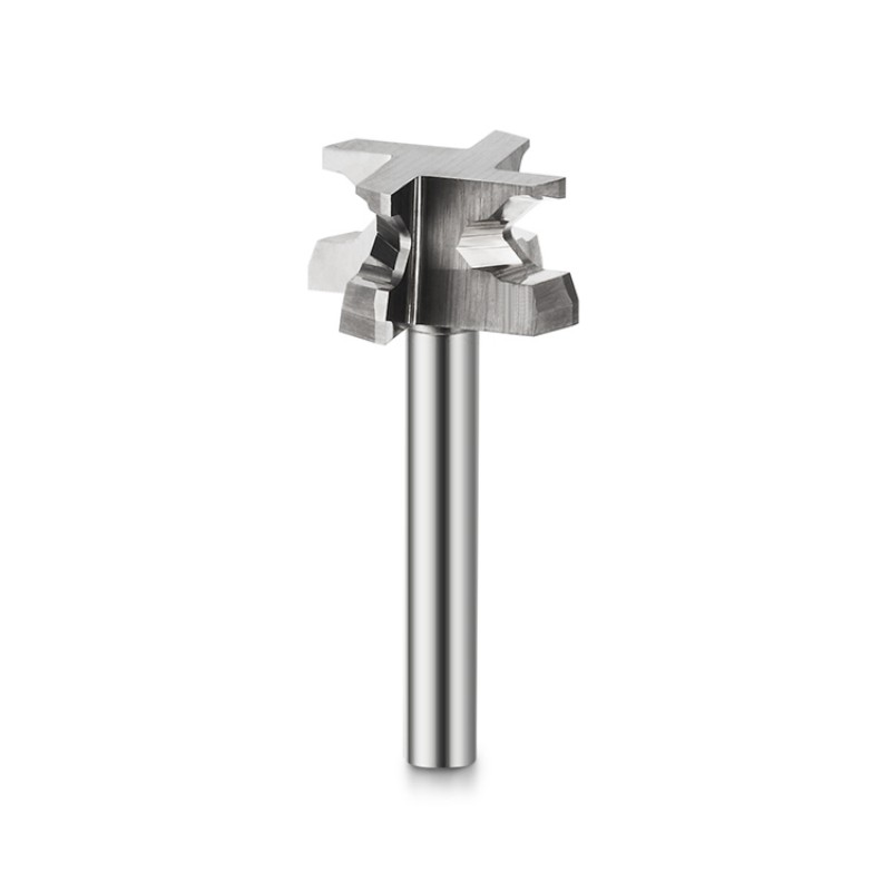
This custom solid carbide form end mill is developed
from the component drawing for machining multiple
diameters, steps, shoulders, chamfers, radii, grooves
and special profile features with one cutting tool.
Unlike a standard square, ball nose or corner radius
end mill, the cutting profile is designed around the
finished component geometry. Combining several adjacent
features in one cutter can reduce tool changes, simplify
the machining sequence and improve the positional
relationship between finished profiles.
Recommended Form Milling Applications
Custom form end mills are suitable for components
containing several connected dimensions or profiles
that would otherwise require multiple standard cutters
and separate machining operations.
Step and Shoulder Machining
Combines different cutting diameters and axial
positions to machine steps, shoulders and
adjacent cylindrical features.
Chamfer and Radius Profiles
Integrates chamfers, convex or concave radii
and profile transitions into the same
cutting-tool geometry.
Groove and Form Milling
Suitable for component-specific grooves,
reliefs, recesses and formed surfaces that
cannot be produced efficiently with standard tools.
Combination Feature Machining
Multiple related features can be machined in
one programmed operation when the component,
machine and tool access permit.
Profiles That Can Be Combined in One Tool
The final cutting profile is designed according to
the component drawing. Different features can be
combined when sufficient tool strength, chip space
and machining access are available.
Why Use a Custom Form End Mill?
A custom form cutter is not always intended to replace
every standard end mill. It is most useful when several
related component features must maintain a stable
dimensional relationship or be produced repeatedly.
Machining Process Benefits
- Combines multiple component profiles in one cutter
- Can reduce the number of tool changes
- Can simplify CNC programming and tool management
- Reduces repeated positioning between separate tools
- Supports shorter and more consistent machining cycles
- Suitable for repeated batch-production applications
Dimensional Control Benefits
- Profiles are ground into one fixed tool relationship
- Helps control axial distance between adjacent features
- Supports repeatable steps, chamfers and radii
- Reduces cumulative positioning errors between tools
- Allows profile inspection against an approved drawing
- Tool compensation can be planned from the actual geometry
Custom Form End Mill vs Multiple Standard Cutters
The best solution depends on production quantity,
component tolerance, setup time and the complexity
of the required profile.
Custom Form End Mill
- Designed around the finished component profile
- Combines several features in one tool
- Reduces tool changes in suitable applications
- Maintains fixed relationships between profiles
- Requires drawing review and custom manufacturing
- Most suitable for repeat production or critical profiles
Multiple Standard End Mills
- Uses separate cutters for each feature
- Provides flexibility for low-volume machining
- Allows individual features to be adjusted separately
- May require additional tool changes and programs
- Can increase cumulative positioning variation
- Suitable when component profiles change frequently
Custom Form End Mill Design and Performance
Cutting profile, carbide grade, flute geometry,
edge preparation, coating and tool dimensions are
developed together according to the component,
workpiece material and machining conditions.
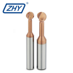
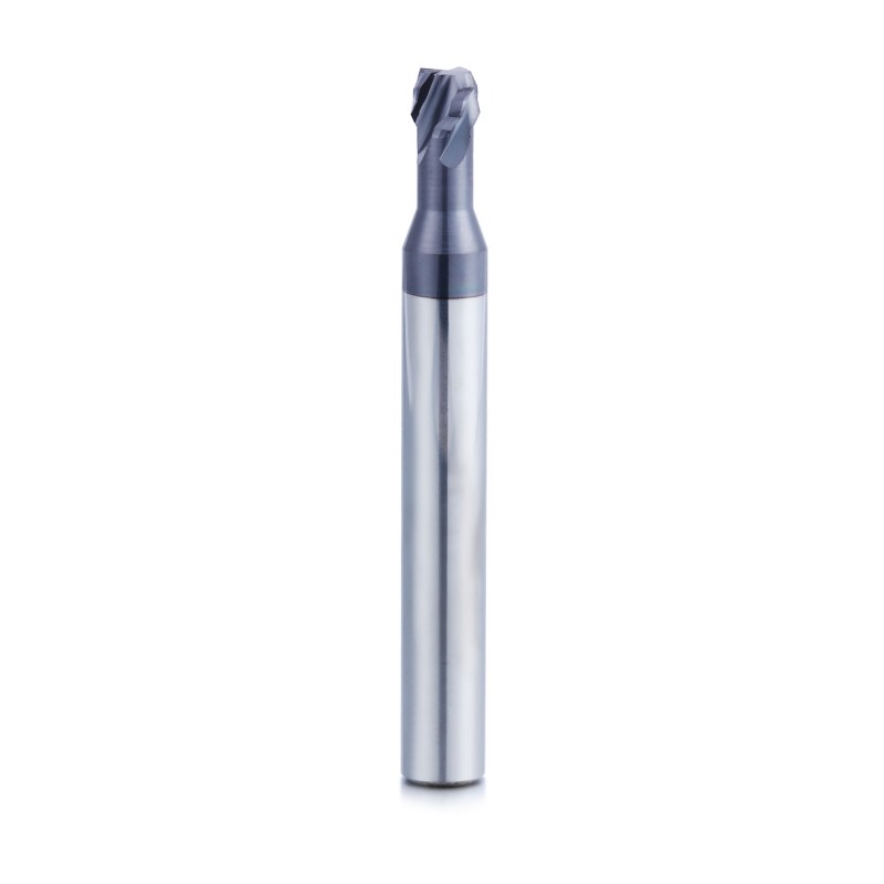
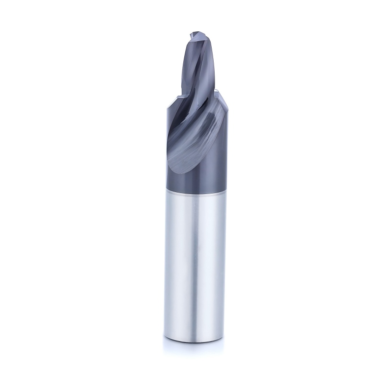
Solid Carbide Construction
Solid carbide provides rigidity, wear resistance
and dimensional stability for precision
form-milling applications.
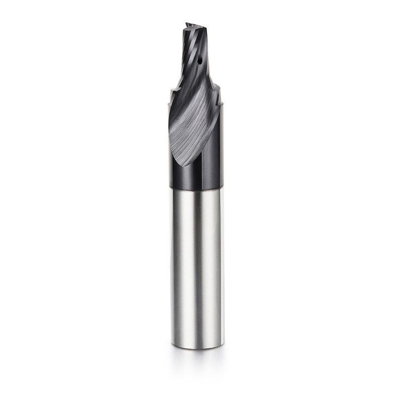
Drawing-Based Profile
Cutting geometry is developed according to
the actual component dimensions rather than
a fixed standard cutter form.
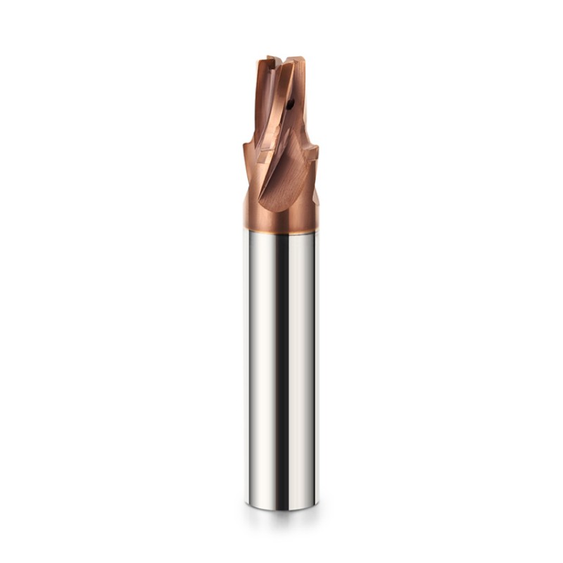
Multiple Diameter Sections
Different cutting diameters can be combined
to produce adjacent steps, shoulders and
cylindrical features.
Combination Form Geometry
Chamfers, radii, grooves, reliefs and other
profiles can be integrated when tool strength
and chip clearance permit.
Controlled Axial Position
Profile locations are ground according to
the approved tool drawing to maintain their
required axial relationship.
Reduced Tool Changes
Combining related features in one cutter can
reduce separate tool calls and simplify the
production sequence.
Custom Flute Configuration
Flute quantity, helix, rake and chip space
can be selected according to material,
profile width and required tool strength.
Custom Relief Geometry
Relief sections can be designed to avoid
interference with nearby component walls,
shoulders and finished surfaces.
Material-Specific Carbide Grade
Carbide grade can be selected according to
workpiece material, hardness, tool dimensions
and cutting-load requirements.
Application-Specific Coating
Coating is selected according to the workpiece
material, cutting temperature, abrasiveness
and coolant condition.
Prototype Tool Support
Prototype cutters can be produced for profile,
dimensional and machining verification before
batch production.
OEM Production Support
Customer model numbers, laser marking,
labels and private-label packaging are
available for distributors and tool brands.
Typical Industry Applications
Custom form end mills can be developed for industries
requiring special component profiles, repeatable batch
production and reduced machining operations.
Available Workpiece Material Applications
The final carbide grade, flute design, edge treatment
and coating should be selected according to the exact
workpiece material and machining conditions.
Hardened steel, titanium alloys, nickel-based alloys
and other difficult-to-machine materials require
a separately evaluated carbide grade, coating,
flute geometry and tool strength.
Available Custom Form End Mill Configurations
This product is manufactured according to an approved
tool drawing. There is no single universal standard size.
| Tool Type | Custom Solid Carbide Form End Mill |
|---|---|
| Alternative Names | Custom Profile End Mill / Solid Carbide Form Milling Cutter / Special Profile Cutter |
| Tool Material | Solid Carbide |
| Cutting Profile | Drawing-Based Custom Form Geometry |
| Cutting Diameter | Custom According to Component Drawing |
| Profile Features | Steps / Shoulders / Chamfers / Radii / Grooves / Reliefs / Combination Forms |
| Flute Configuration | Selected According to Profile, Material and Chip-Space Requirements |
| Cutting Length | Drawing-Based Custom Length |
| Neck and Relief | Standard or Custom Clearance Geometry |
| Shank Diameter | Standard or Customized |
| Overall Length | Standard or Customized |
| Coating | Selected According to Workpiece Material and Machining Conditions |
| Main Operations | Form Milling / Step Milling / Profile Machining / Combination Feature Machining |
| Custom Options | Profile / Diameter / Step Position / Chamfer / Radius / Groove / Flute Geometry / Shank / Overall Length |
| OEM Options | Laser Marking / Customer Model Number / Custom Label / Private-Label Packaging |
Final dimensions, tolerances and profile definitions
must be confirmed on the approved tool drawing
before prototype or batch production.
Custom Tool Design Considerations
Not every component feature should automatically be
combined into one cutter. Tool strength, chip evacuation,
grinding accessibility and machining load must be evaluated.
Profile and Strength Review
- Minimum and maximum cutting diameters
- Distance between profile features
- Smallest neck or core diameter
- Required radii and sharp-corner transitions
- Effective cutting length and tool overhang
- Expected radial and axial cutting load
Manufacturing and Machining Review
- Grinding-wheel access to each profile
- Flute and chip-space requirements
- Tool entry and exit path
- Workpiece and holder interference
- Profile inspection method
- Prototype and batch-production quantity
Recommended Machining Method
Form milling performance depends on rigid workholding,
low tool runout, controlled engagement and a toolpath
developed around the actual cutter profile.
Recommended Setup
- Use a rigid machine and stable workholding system
- Use a low-runout collet or toolholder
- Program from the approved cutter drawing
- Use controlled radial and axial engagement
- Provide suitable chip evacuation and coolant
- Inspect the first component before batch production
Conditions Requiring Attention
- Excessive load on a narrow profile section
- Incorrect axial position of the form cutter
- Insufficient clearance near component shoulders
- Excessive tool overhang or machine vibration
- Poor chip evacuation around wide profile sections
- Programming based on nominal instead of actual geometry
Information Required for Tool Development
Complete component and machining information helps
determine whether the required profiles can be combined
safely and efficiently in one solid carbide cutter.
Component Information
- 2D drawing or 3D component model
- All required profile dimensions
- Dimensional and profile tolerances
- Workpiece material and hardness
- Surface-finish requirement
- Annual or batch production quantity
Machining Information
- Machine type and spindle interface
- Toolholder type and measured runout
- Required machining sequence
- Available spindle-speed and feed range
- Coolant, air-blast or dry-machining condition
- Current tools, parameters and machining problems
Custom Form End Mill Development Process
Custom geometry is reviewed and confirmed before
prototype manufacturing and batch production.
Production and Quality Inspection
Tool diameter, step position, form profile,
flute geometry and cutting-edge condition are inspected
against the approved tool drawing.
Custom Solid Carbide Form End Mill Manufacturer
ZHY supplies drawing-based solid carbide form end mills
to precision machining companies, automotive suppliers,
aerospace manufacturers, mold companies, distributors
and private-label cutting-tool brands.
Engineering and Production Support
- Component and tool drawing review
- Combination-profile feasibility analysis
- Custom carbide, geometry and coating selection
- Prototype tools for dimensional verification
- Application review after machining trials
- Repeat batch production after approval
OEM and Private Label
- Customer logo laser marking
- Customer model and product numbers
- Drawing and revision-number management
- Custom labels and barcode stickers
- Private-label packaging support
- Packaging verification before shipment
Explore More Custom Milling Tools
Browse additional drawing-based and special-purpose
carbide milling cutters for complex component features.
Request a Custom Form End Mill Quote
Send us the component drawing, required profile,
dimensional tolerances, workpiece material, hardness,
machine information, toolholder, cutting conditions,
current machining process and order quantity.
Our team will review the application and develop
a suitable custom solid carbide form end mill.